Notice – Thermo Pride Spirit Gas TG9S Single Stage PSC 95.5% User Manual
Page 17
1083287-UIM-A-0114
Johnson Controls Unitary Products
17
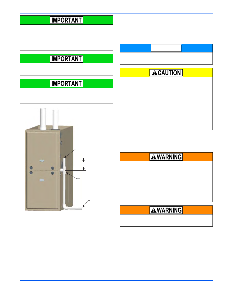
The condensate will flow to the drain better if an open stand pipe is
installed in the drain line. See Figure 23.
If evaporator coil or humidifier drains are combined with the furnace
drain, then the open stand pipe could be raised higher, above the 5”
minimum.
Do not drain other devices (humidifier, evaporator coil, etc.) into the top
opening of the vent stand pipe. Instead, install a second tee in the
vented drain tube below the furnace drain tee and route additional
drainage through the new tee.
CONDENSATE DRAIN TERMINATION
A condensate sump pump MUST be used if required by local codes, or
if no indoor floor drain is available. The condensate sump pump must
be approved for use with acidic condensate.
The furnace, evaporator coil, and humidifier drains may be combined
and drained together. The evaporator coil drain may have an exter-
nal, field-supplied trap prior to the furnace drain connection to prevent
conditioned air leakage. All drain connections (furnace, evaporator
coil, or humidifier) must be terminated into an open or vented drain as
close to the respective equipment as possible. Regular maintenance
is required on condensate drainage system.
Condensate must be disposed of properly. Follow local plumbing
or wastewater codes. The drain line must maintain a 1/4" per foot
(20 mm per m) downward slope to the drain.
If an external vent tee is being installed, then it must have its own
condensate trap before it is disposed into an open or vented drain.
This is not to be considered as a second trap as referenced else-
where in this document.
FIGURE 23: Typical. Condensate Drain, Vertical Installation
To Open Or
Vented Drain
Tee
5” Min.
Open Stand Pipe
(Anti-siphon air vent)
A loop has been added to the pressure switch vacuum hose. How-
ever, ensure that all pressure switch hoses are routed such that they
prevent any condensate from entering the pressure switch.
It is possible for condensation to form inside the combustion air
(intake) pipe in the summer months if significant length of combus-
tion air pipe passes through conditioned space. This problem can
be averted by installing the supplied vent drain and drain hose
located in the loose parts bag. The intake drain hose is to be
installed by connecting it to the inlet pipe coupling and to the collec-
tor box as shown in Figures 24, 26, and 27. The drain hose must
not sag or droop after it is installed. If glue is used when connecting
the intake pipe to the intake coupling, the drain opening in the vent
drain must not be plugged. If the intake drain is used, the bird
screen cannot be installed. This is only approved for upflow and
horizontal applications when the intake pipe is located on the top of
the furnace. This is true for all long horizontal venting in any furnace
configuration. This will keep condensate from entering the furnace.
DO NOT terminate the condensate drain in a chimney, or where the
drain line may freeze. If the drain line will be exposed to temperatures
below freezing, adequate measures must be taken to prevent the
drain line from freezing. Failure to provide proper protection from
freezing can result in improper operation or damage to the equipment
and possible property damage. When exposed to temperatures
below freezing, use of a 3 to 6 watt per foot at 115 VAC, 40°F (4.4°C)
self-regulating, shielded and waterproof heat tape is recommended
on the drain line outside the furnace.
DO NOT trap the drain line at any location. The furnace has a con-
densate drain trap built into the drain pan.
Liquid anti-freeze will cause damage to internal plastic parts of this
furnace. DO NOT attempt to winterize the furnace using liquid
anti-freeze.
NOTICE