Thermo Pride Spirit Gas TG9S Single Stage PSC 95.5% User Manual
Page 6
1083287-UIM-A-0114
6
Johnson Controls Unitary Products
COIL INSTALLATION
COIL/FURNACE ASSEMBLY - MC/FC/PC SERIES
COILS
FURNACE ASSEMBLY - MC & FC SERIES COILS
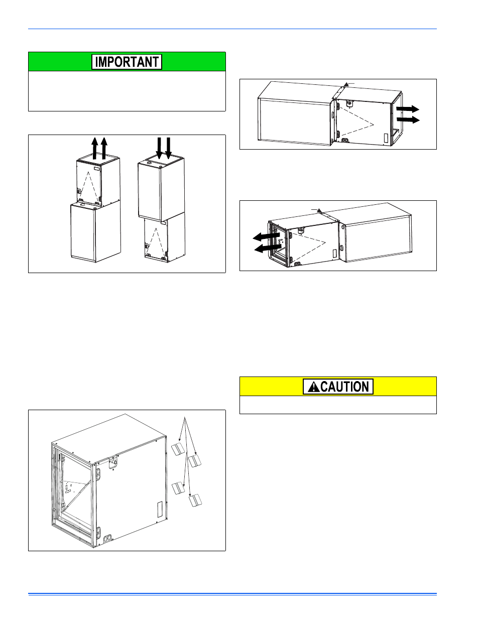
These coils are factory shipped for installation in either upflow or down-
flow applications with no conversion.
Position the coil casing over or under the furnace opening as shown in
Figure 2 after configuring coil flanges as required see “Coil Flange” sec-
tion below.
COIL FLANGE INSTALLATION
The coil cabinet includes four removable flanges to allow proper fit up
with furnaces having inlet and outlet configurations. The flanges are
attached to the inside top of the coil cabinet in the factory during pro-
duction. The flanges are rotated down for shipment. In order to use the
flanges, remove the screw holding an individual flange, rotate the flange
so it is in the upward position, and reinstall the screw. Repeat the proce-
dure for all 4 flanges. See Figure 3.
FURNACE ASSEMBLY - MC SERIES COILS ONLY
MC coils are supplied ready to be installed in a horizontal position. A
horizontal pan is factory installed. MC coils should be installed in all hor-
izontal applications with the horizontal drain pan side down.
For horizontal left hand applications no conversion is required to an MC
coil when used with a downflow/horizontal furnace. A mounting plate,
supplied with every coil should always be installed on the side desig-
nated as top side. See Figures 4 & 5.
FURNACE ASSEMBLY - PC SERIES COILS
These upflow coils are designed for installation on top of upflow fur-
naces only.
If the coil is used with a furnace of a different size, use a 45° transition
to allow proper air distribution through the coil.
1.
Position the coil casing over the furnace opening as shown in Fig-
ure 6.
2.
Place the ductwork over the coil casing flange and secure.
3.
Check for air leakage between the furnace and coil casing and seal
appropriately.
On all installations without a coil, a removable access panel is recom-
mended in the outlet duct such that smoke or reflected light would be
observable inside the casing to indicate the presence of leaks in the
heat exchanger. This access cover shall be attached in such a man-
ner as to prevent leaks.
FIGURE 2: Vertical Applications
FIGURE 3: Coil Cabinet Attachment Flanges
UPFLOW
DOWNFLOW
Furnace
Furnace
ATTACHMENT FLANGES
FIGURE 4: Horizontal Right Application
FIGURE 5: Horizontal Left Application
Do not drill any holes or drive any screws into the front duct flange on
the coil in order to prevent damaging coil tubing. See Figure 6.
Furnace
Mounting Plate
Furnace
Mounting Plate