Panel descriptions, Top panel – Roland AeroCaster Livestreaming System User Manual
Page 4
Panel Descriptions
4
Panel Descriptions
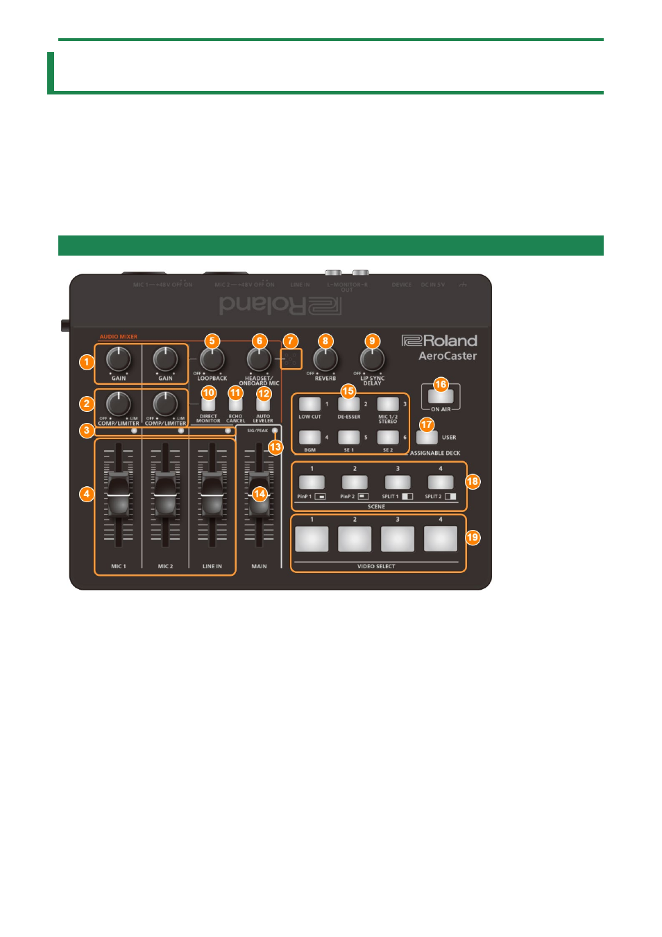
This section explains the names of the components of the VRC-01 and how each one works.
Side Panel(P.9)
Top Panel
1.
MIC [GAIN] knob (MIC 1, 2)
2.
[COMP/LIMITER] knob (MIC 1, 2)
Adjusts the baseline level from which the compressor operates for the MIC 1 and MIC 2 inputs.
The limiter operates when the knobs are turned all the way clockwise.
The compressor turns off when the knobs are turned all the way counterclockwise.
Compressor:
Audio that exceeds the specified threshold level is compressed. This reduces the difference between the maximum volume
and minimum volume, making the audio more comfortable for listening.
Limiter:
Keeps excessive input signals down to an appropriate level to prevent the sound from clipping.
3.
SIG/PEAK indicators (MIC 1, 2/LINE IN)
These light up green or yellow when audio input is detected. If the input signal is excessive, the indicators light up red.
4.
[MIC 1] [MIC 2] [LINE IN] faders
These adjust the input levels for MIC 1/MIC 2/LINE IN.