AMX MT-1002 Modero G5 Tabletop 10.1" Multi-Touch Panel User Manual
Page 29
Modero G5 Touch Panels - Installation & Hardware Reference Manual
29
| TOC
2. Thread the incoming cables (Ethernet and Micro-USB) from their terminal locations through the surface opening, leaving
enough slack in the wiring to accommodate any re-positioning of the panel.
3. Remove the Backbox knockouts and thread incoming cables through the knockout holes.
4. Gently push the Backbox into the mounting surface.
•
This Backbox uses two Locking Tabs to secure the Backbox to the wall. For typical mounting surfaces, such as drywall, the
locking tabs are the primary method for securing the Backbox to the wall.
•
To ensure a stable installation, the thickness of the wall material must be a minimum of .50 inches (1.27cm) and a
maximum of .875 inches (2.22cm). The mounting surface should also be smooth and flat. For thin walls or solid surfaces,
use mounting screws (not included) -
see FIG. 20
.
5. Extend the Locking Tabs by tightening the Locking Tab screws until snug.
FIG. 25 and FIG. 26
show the Locking Tabs
on the Modero Wall Mount Backboxes:
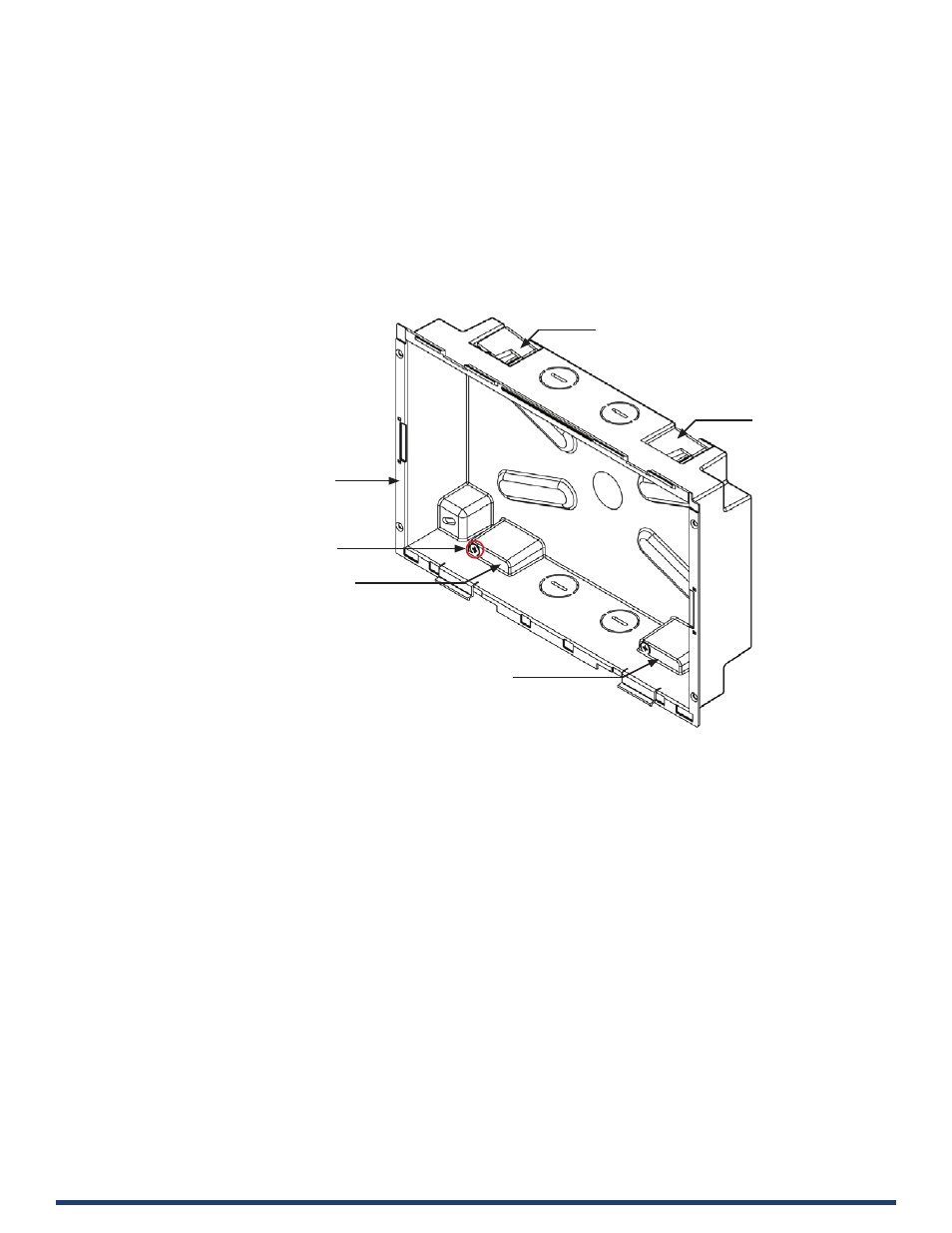
FIG. 25 MD-1002 Backbox - Locking tab and locking tab screws (X4)
Locking Tab (X4)
Locking Tab (X4)
Locking Tab (X4)
Locking Tab (X4)
Locking Tab screw (x4) - tighten to extend
each of the four Locking Tabs
(max torque = 5 IN-LB)
10.1” Wall Mount Backbox