8 - input and speaker connections, Connections, Fx amplifier • operating manual connections – Ashly FX60.2 Multipurpose Installation Network Amplifier with DSP (1 RU, 1/2 Rack) User Manual
Page 15
15
FX Amplifier • Operating Manual
Connections
8. Connections
8.1 Mains Power Connection
FX amplifiers incorporate a power factor
corrected universal power supply and can be
used with mains input voltage from 100VAC
to 240VAC, 50/60Hz. Use the mains cable
supplied with the amplifier.
FX
half-rack
amplifiers have no mains power
switch and are operational as soon as mains
power is connected. Ensure that all signal,
GPIO and output connections are made before
connecting the amplifier to mains power.
8.2 Input Connections
All FX amplifier models provide four balanced
or unbalanced analog audio inputs and a
stereo S/PDIF digital audio input. Any input
channel can be routed to any zone using the
Zone>Source menu. See Sections
Analog Inputs
FX analog inputs are of line level format
with a default input sensitivity of +4dBu (full
output voltage swing/sensitivity) in all output
modes. Input signal levels up to +24dBu can
be handled without input clipping. Input
sensitivity options are set via the amplifier
network interface Input>Sensitivity menu. See
•
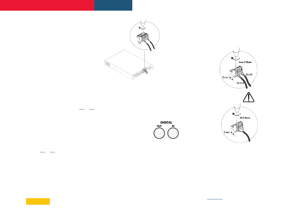
Balanced input connections to the
amplifiers are made via male ‘Euro Block’
connectors. Connecting cables to the
supplied female input connectors is
illustrated in Diagram 8.2.
•
Unbalanced input connections to the
amplifiers are made via RCA phone jacks.
Diagram 8.2:
Balanced Input connections
Note: 2 channel amplifier model connections
differ from 4 channel models only in the
deletion of channel 3 and channel 4 output
connectors. Input and GPIO connections
remain the same between all FX models.
Digital Input/Output
FX offers a S/PDIF
stereo digital audio input
connection via a single RCA
Phone jack.
A S/PDIF digital audio output jack is also fitted.
The S/PDIF output signal by default reflects
the input to amplifier installation zones A & B
and is intended to be used for daisy chaining FX
amplifiers.
Note: 75Ω RCA Phono cables specifically
intended for digital audio should always be
used for S/PDIF connections. Standard Phono
cables can be used but may not result in
optimal performance.
8.3 Output Speaker Connections
Output connections from the amplifiers are
achieved via male ‘Euro Block’ connectors.
Ensure that speaker connection polarity is
correct throughout the installation:
•
In the case of Low-Z
speaker connections,
positive (+)
amplifier terminals
should always be
connected to positive
speaker terminals
and negative (–)
amplifier terminals
always connected
to negative speaker
terminals.
•
In the case of Hi-Z (70V or 100V)
speaker connections,
the two speaker
cable conductors
should be connected
between the positive
(+) terminal of Output
1 and the negative
terminal (-) of Output
2, and likewise for
Outputs 3 and 4.
•
Output mode options (Low-Z or Hi-Z)
are configured via the amplifier network
interface in the Output>Speaker
Preset>Output Mode menu.
Note: The exclamation point printed next to the output
terminals of the amplifiers is, in addition to the CLASS
2 WIRING text, intended to alert users to the risk of
hazardous voltages. Output connectors that could
pose a risk are marked with the exclamation point. Do
not touch the output terminals while the amplifier is
switched on. Make all connections with the amplifier
switched off. See
of this manual.
5 mm