2 - carton contents, Carton contents, Fx amplifier • operating manual – Ashly FX60.2 Multipurpose Installation Network Amplifier with DSP (1 RU, 1/2 Rack) User Manual
Page 6: Overview
6
FX Amplifier • Operating Manual
1.2 Connections
FX amplifier audio input and output
connections are accomplished via Euroblock,
RCA Phono, and RCA S/PDIF connectors. A
GPIO (General Purpose In/Out) Euroblock
connector enables certain amplifier functions
to be controlled remotely. FX amplifiers provide
both their own WiFi hotspot and RJ45 Ethernet
LAN connection for software configuration.
Note: Half-rack FX amplifiers have no mains power
switch and are operational as soon as mains power
is connected via the IEC 60320 mains socket.
1.3 Network Features
FX amplifiers are TCP/IP network connected
devices that require a wireless or wired network
connection to access their configuration
menus. The configuration menus are accessed
via a web page
interface served
up directly by the
amplifier, so there
is no application to
install. The interface
offers access to the
main Dashboard,
plus Input, Zone,
Output, and General
Settings.
The configuration menus are fully described in
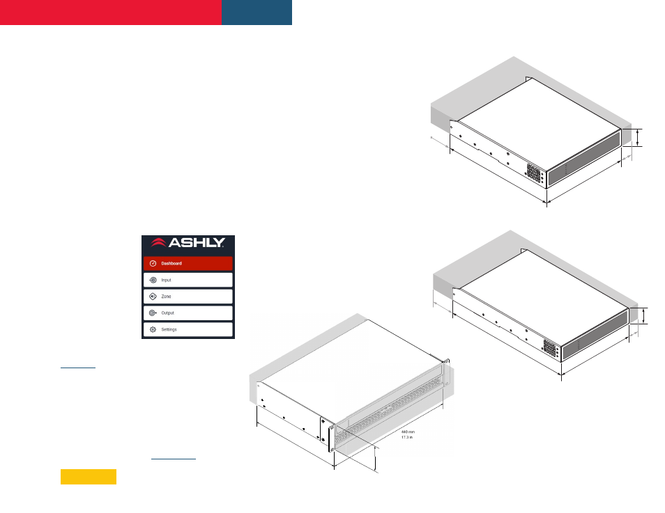
1.4 Dimensions
FX amplifier dimensions and ventilation
requirements are illustrated in Diagrams 1a, 1b,
and 1c. All models are fan-cooled and must be
installed such that ventilation apertures are not
obstructed. Half-rack models can be fitted for full-
rack, under-desk, or wall-mounting by purchasing
an optional mounting kit. (
2. Carton Contents
FX amplifiers are shipped in a cardboard carton
containing the amplifier unit, a mains cable
appropriate for the sales territory, an accessory
pack, and a document pack. The full contents is
listed below.
- Amplifier unit
- Mains power cable
- Input connector x 2
- GPIO socket connector
- Output connector x 1 or 2
- Adhesive rubber feet x 4
- Document pack
Overview
Diagram 1b
FX Half-Rack
two
channel amplifier dimensions.
Shaded area defines ventilation space
Diagram 1c
FX Half-Rack
four
channel amplifier dimensions.
Shaded area defines ventilation space
80mm
3.1in
213mm
8.4in
25mm
1.0in
220mm
8.7in
44mm
1.7in
80mm
3.1in
319mm
12.6in
25mm
1.0in
220mm
8.7in
44mm
1.7in
440 mm
17.3 in
332 mm
13.1 in
88 mm
3.5 in
Diagram 1a
FX 2U Full-Rack two & four channel
amplifier dimensions. Shaded area
defines ventilation space