10 - signal flow and panel diagrams, Fx amplifier • operating manual, Diagrams – Ashly FX60.2 Multipurpose Installation Network Amplifier with DSP (1 RU, 1/2 Rack) User Manual
Page 18
18
FX Amplifier • Operating Manual
Analog 3
Output
Matrix
Zones A - D
Outputs 1 - 4
Analog 2
Input
Sensitivity
Analog 1
Input
Gain
Input
Sensitivity
Input
Gain
Input
Sensitivity
Input
Gain
Analog 4
SPDIF In (stereo)
Pink Noise
Gain
Dela
y
Le
v
el
Adjustment
Le
v
el
Adjustment
Le
v
el
Adjustment
Le
v
el
Adjustment
Compressor
Compressor
Compressor
Compressor
Dela
y
Dela
y
Dela
y
EQ
EQ
EQ
EQ
EQ
EQ
EQ
EQ
Polarity
Polarity
Polarity
Polarity
Limiter
BTL
Amplifier
2 x Low-Z
1 x Hi-Z
BTL
Amplifier
2 x Low-Z
1 x Hi-Z
Limiter
Limiter
Limiter
Driver
Alignment
Driver
Alignment
Driver
Alignment
Driver
Alignment
Crossover
Crossover
Crossover
Crossover
Gain Trim
Gain Trim
Gain Trim
Gain Trim
Input
Sensitivity
Input
Gain
Input
Gain
Input
Selection
Input Setup
Zone Setup & Routing
Output Setup
Output 1
Output 2
Output 3
Output 4
Room Adjustment Parameters
Speaker Adjustment Parameters
S/PDIF Out (stereo)
Inputs To
Zones
A & B
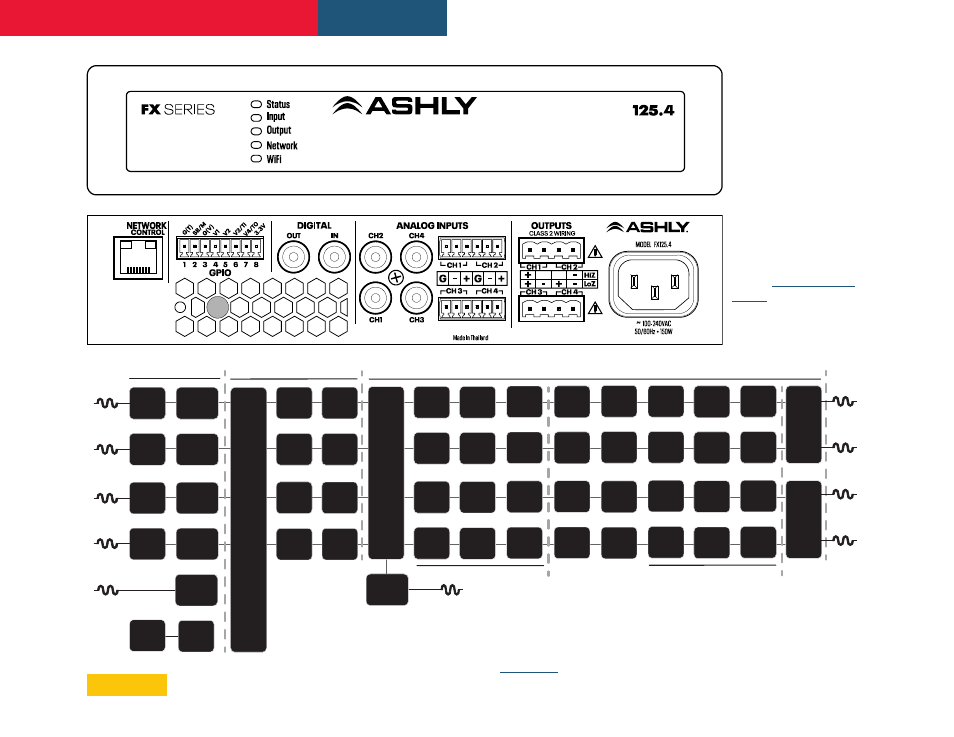
Diagram 10.1:
FX Front & Back Panels,
(FX125.4 shown)
Note: 2-Channel
models are the same as
4-channel models other
than power ratings and
number of available zones
and speaker outputs.
All Network, Input,
GPIO connections, and
functionality are the same
between FX models.
NOTE:
the same features and
connections as half-rack
models.
Diagram 10.2:
Signal Flow Diagram (4-channel model is shown).
Note
: On two-channel models, all four inputs are available, but only
Zones A & B are used for providing signal to the two speaker outputs.
Note
signal is always taken from
the inputs to Zones A & B.
10. Diagrams