New prod uc t zxbm5210, Zxbm5210 – Diodes ZXBM5210 User Manual
Page 5
ZXBM5210
Document number: DS36765 Rev. 1 - 2
5 of 17
December 2013
© Diodes Incorporated
NEW PROD
UC
T
ZXBM5210
Application Note
Rotation Control and Standby Modes
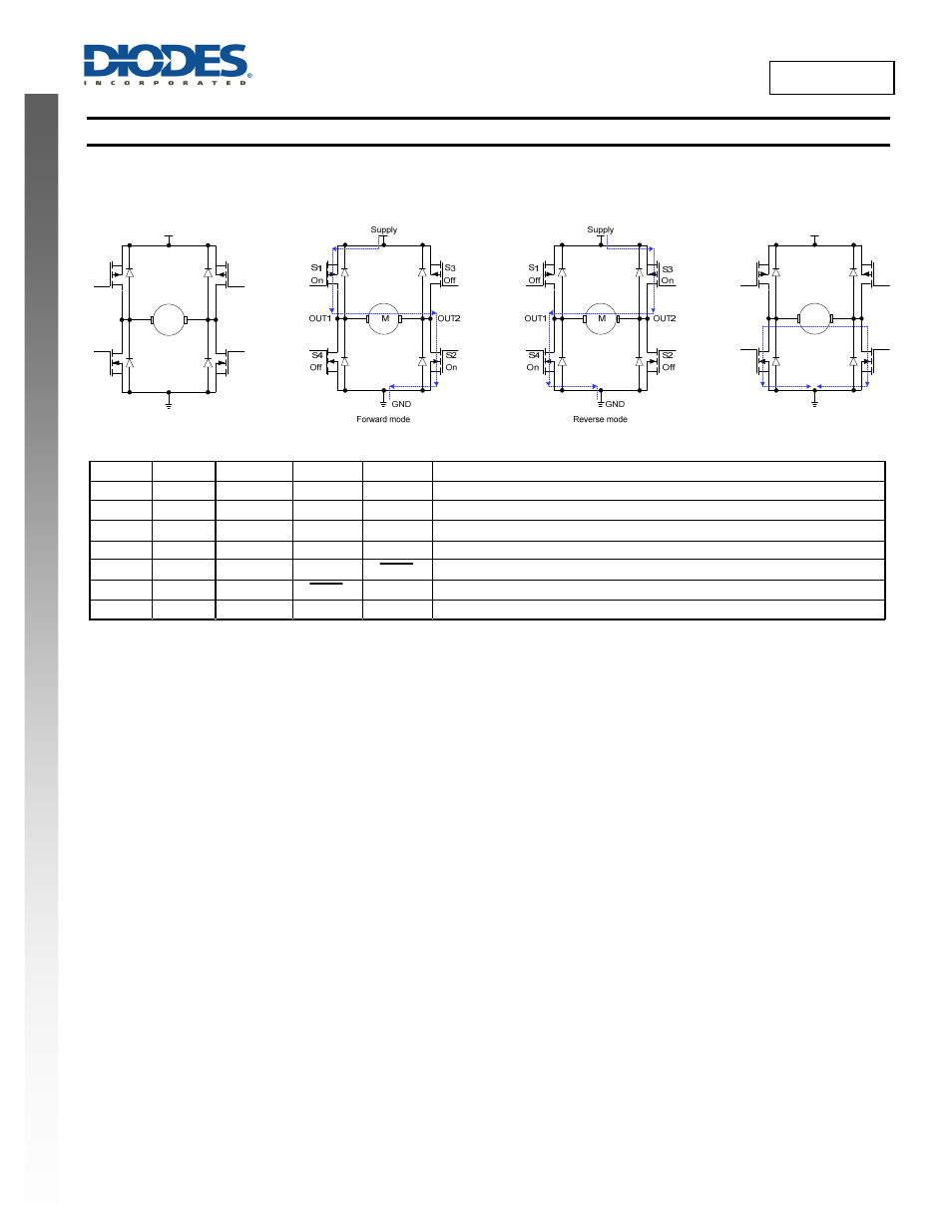
The device has FWD and REV pins for controlling the motor rotation directions. The device has four motor operation modes: 1) Standby mode,
2) Forward mode, 3) Reverse mode and 4) Brake mode. The four modes are controlled by the FWD and REV logic pins.
FWD REV V
REF
OUT1 OUT2
Operating
mode
L
L
x
Open
Open
Standby mode – All switches are off
H L
3V to V
DD
H L
Forward mode – Current flows from OUT1 to OUT2; V
REF
duty control
L H
3V to V
DD
L H
Reverse mode – Current flows from OUT2 to OUT1; V
REF
duty control
H
H
x
L
L
Brake mode – Short circuit brake with low side switches on
PWM L V
DD
H PWM
Forward mode – Current flows from OUT1 to OUT2; PWM control mode
L PWM V
DD
PWM H
Reverse mode – Current flows from OUT2 to OUT1; PWM control mode
H
H
x
L
L
Brake mode – Short circuit brake with low side switches on
In the brake mode, switches S2 and S4 are ON allowing the motor to stop quickly. All the internal control circuits are fully operational.
In the standby mode all the output drive switches are off and additionally, the internal circuits are also turned off to minimize power consumption.
The power consumption in the standby mode is less than in the brake mode. If running motor enters the Standby mode, due to the body diodes
the motor free wheels to idle state. Whenever the motor enters the standby mode from any mode (except the brake mode) the control logic will
remain active in previous mode for at least 125µs before shutting down the internal circuits. To prevent device entering the standby mode during
operating mode changes, the mode change signals should be completed within 125µs.
In the forward mode, with switches S1-S2 ON and S3-S4 OFF, OUT1 is high and OUT2 is low. The motor current flows from OUT1 to OUT2. In
the reverse mode, switches S1-S4 are ON while S1-S2 are OFF to allow motor current flow from OUT2 to OUT1.
In the forward or reverse mode, for V
REF
speed control, the output drive duty ratio is generated internally based on the voltage on the V
REF
pin.
For PWM speed control, external PWM signals applied to the FWD or REV pins control the PWM switching of the low side S2 (forward mode)
or S4 (reverse mode). See application section for further details.
The ZXBM5210 has three modes of speed control: V
REF
speed control mode, PWM speed control mode and by adjusting the supply voltage
M
S1
S2
S4
Off
Off
Off
Standby mode
GND
S3
Off
Supply
OUT1
OUT2
S1
S2
S3
S4
On
On
Off
Off
Brake mode
M
Supply
GND
OUT2
OUT1