Carrier INDUCED COMBUSTION 58YAV User Manual
Page 4
14. If furnace is operating properly, REMOVE TAPE TO RE-
LEASE BLOWER ACCESS DOOR SWITCH, replace
blower access door.
Step 3—Cleaning Heat Exchanger
The following steps should be performed by a qualified service
technician:
NOTE:
If the heat exchangers get a heavy accumulation of soot
and carbon, they should be replaced rather than trying to clean
them thoroughly due to their intricate design. A build-up of soot
and carbon indicates that a problem exists which needs to be
corrected, such as improper adjustment of manifold pressure,
insufficient or poor quality combustion air, incorrect size, or
damaged manifold orifice(s), improper gas, or a restricted heat
exchanger. Action must be taken to correct the problem.
If it becomes necessary to clean heat exchanger because of light
dust or corrosion proceed as follows:
1. Turn gas and electrical power to furnace to OFF.
2. Remove control access door.
3. Disconnect vent connector from furnace flue collar.
4. Remove 2 screws that secure relief box. (See Fig. 2.)
5. Disconnect wires to the following components. Mark wires to
aid in reconnection of:
a. Blocked vent safeguard switch.
b. Inducer motor.
c. Pressure switch.
d. Limit overtemperature switch(es).
e. Gas valve.
f. Hot surface ignitor.
g. Flame-sensing electrode
h. Flame rollout switch(es), if applicable.
6. Remove complete inducer assembly and relief box from
furnace.
7. Remove 8 screws that secure flue collector box to center
panel. Be careful not to damage collector box.
8. Remove burner assembly and cell inlet plates. IMPORTANT:
Replace screws in center panel before cleaning.
NOTE:
Be very careful when removing burner assembly to avoid
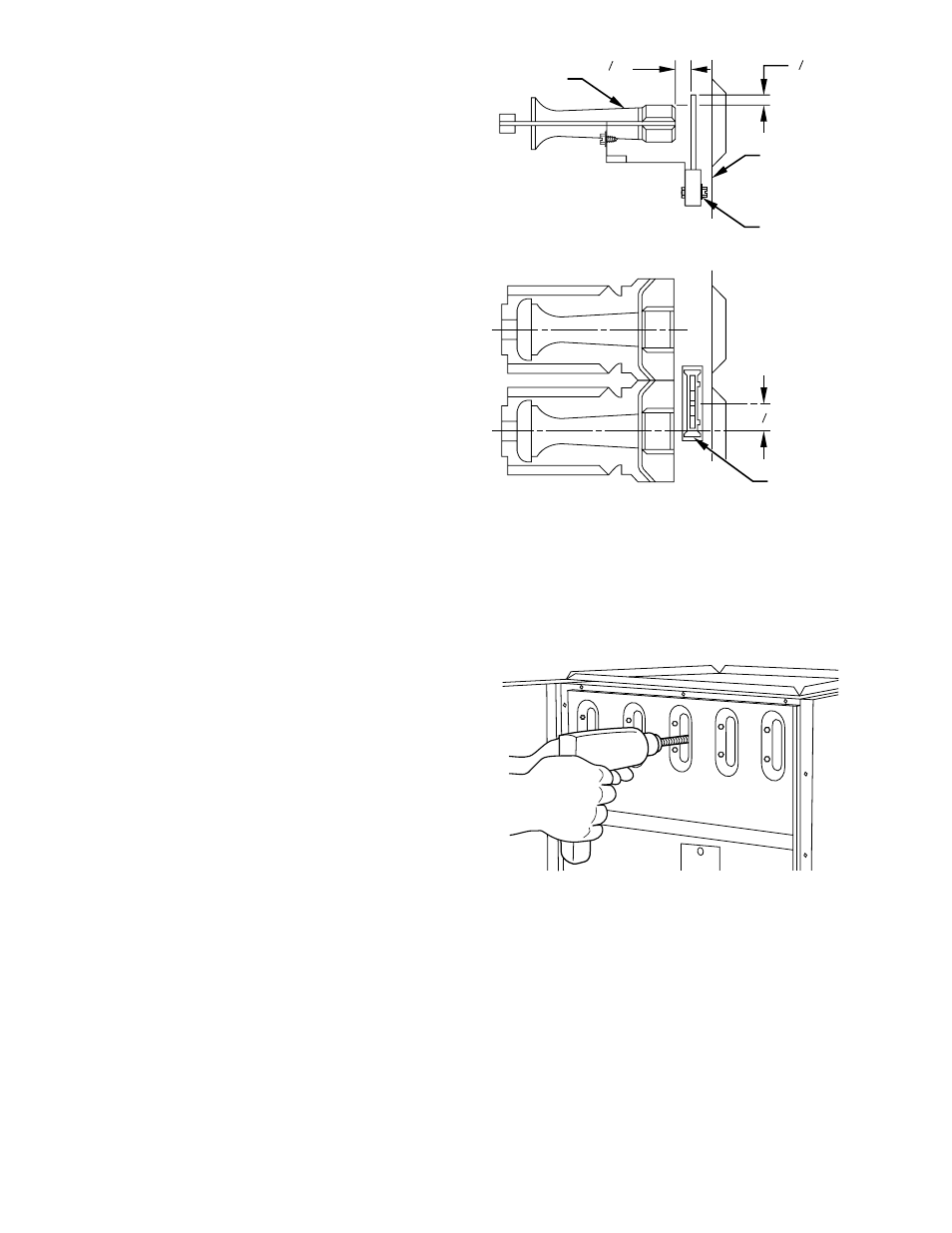
breaking ignitor. See Fig. 3 for correct ignitor location.
9. Using field-provided small wire brush, steel spring cable,
reversible electric drill, and vacuum cleaner, clean cells as
follows:
a. Assemble wire brush and steel spring cable.
(1.) Use 48 in. of 1/4-in. diameter high-grade steel spring
cable (commonly known as drain clean-out or Roto-
Rooter
t
cable).
(2.) Use 1/4-in. diameter wire brush (commonly known as
25-caliber rifle cleaning brush).
NOTE:
The materials needed in items (1.) and (2.) can usually be
purchased at local hardware stores.
(3.) Insert twisted wire end of brush into end of spring
cable, and crimp tight with crimping tool or strike with
ball-peen hammer. TIGHTNESS IS VERY IMPOR-
TANT.
(4.) Remove metal screw fitting from wire brush to allow
insertion into cable.
b. Clean each heat exchanger cell.
(1.) Attach variable-speed, reversible drill to end of spring
cable (end opposite brush).
(2.) Insert brush end of cable into upper opening of cell
and slowly rotate with drill. DO NOT force cable.
Gradually insert at least 36 in. of cable into 2 upper
passes of cell. (See Fig. 4.)
(3.) Work cable in and out of cell 3 or 4 times to obtain
sufficient cleaning. DO NOT pull cable with great
force. Reverse drill and gradually work cable out.
(4.) Insert brush end of cable in lower opening of cell, and
proceed to clean 2 lower passes of cell in same manner
as 2 upper passes.
(5.) Repeat foregoing procedures until each cell in furnace
has been cleaned.
(6.) Using vacuum cleaner, remove residue from each cell.
(7.) Using vacuum cleaner with soft brush attachment,
clean burner assembly.
(8.) Reinstall cell inlet plates and burner assembly. Care
must be exercised to center burners in cell openings.
Fig. 3—Position of Ignitor to Burner
A93347
BURNER
IGNITOR
11 32
"
7 8
"
C
L
C
L
IGNITOR
ASSEMBLY
CELL
PANEL
BURNER
13 32
"
HOT
SURFACE
IGNITOR
ASSEMBLY
Fig. 4–Cleaning Heat Exchanger Cell
A91252
4