Assembly – Ryobi BTS10S User Manual
Page 17
17
ASSEMBLY
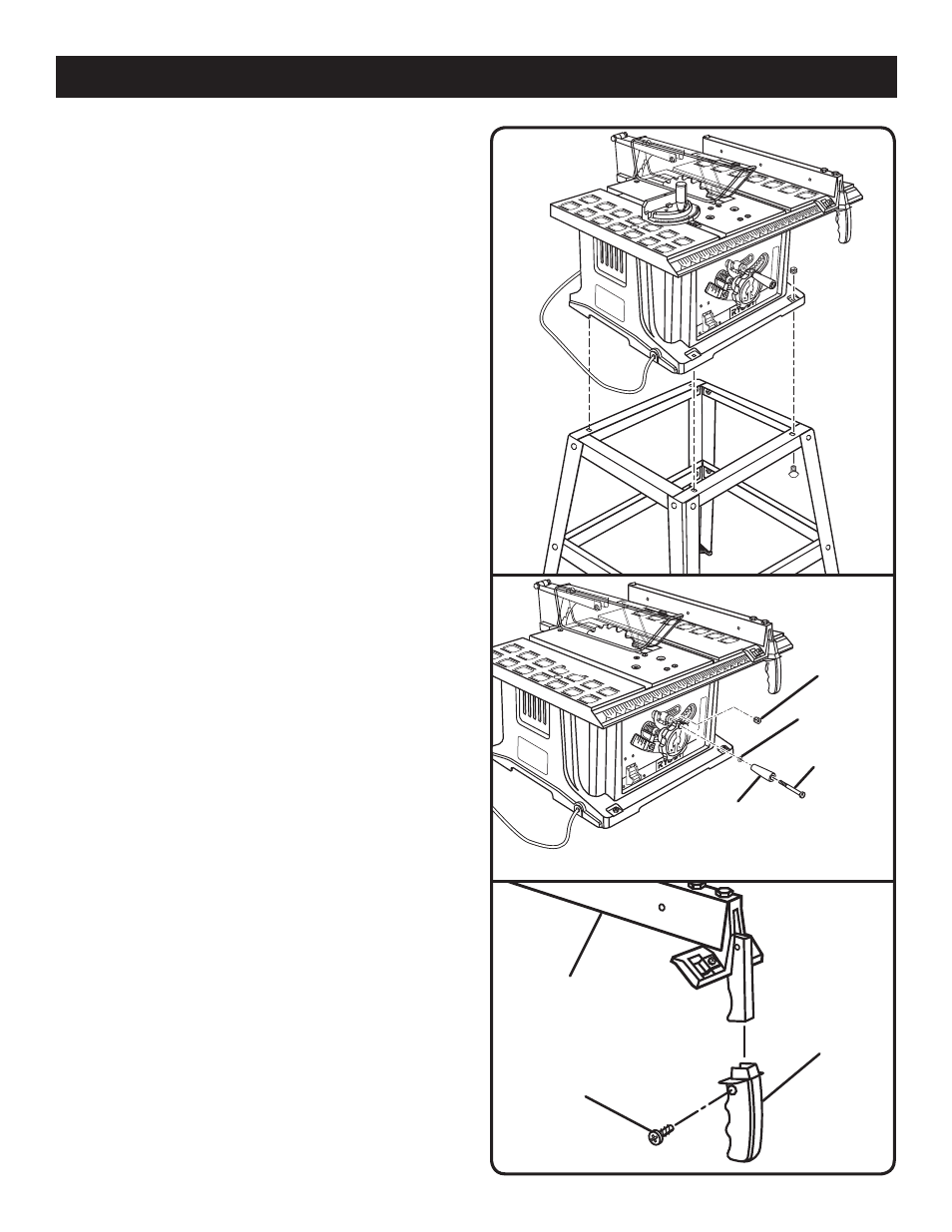
SHOULDER
BOLT
LOCK NUT
BLADE
ADJUSTING
HANDLE
WASHER
MOUNTING THE LEG STAND ON THE TABLE
SAW BASE
See Figure 7.
Do not lift the saw without help. The saw base weighs ap-
proximately 42 lbs. Hold it close to your body. Keep your
knees bent and lift with your legs, not your back. Ignoring
these precautions can result in back injury.
Take the following from a small hardware pack:
4 carriage bolts (1/4-20 x 1-5/8 in.)
4 hex nuts (1/4-20)
NOTE: This hardware was in the pack with hardware for
assembling the leg stand and leveling feet.
Place the leg stand on the table saw base. Align the holes
in the table with the holes in the end braces.
Place a bolt in each hole. Secure with a hex nut. Hand
tighten.
Repeat for three remaining holes. Tighten all hardware
with a wrench.
MOUNTING HOLES
The table saw must be mounted to a firm supporting surface
such as a workbench or leg stand. Four bolt holes have
been provided in the saw’s base for this purpose. Each of
the four mounting holes should be bolted securely using
3/8 in. machine bolts, lock washers, and hex nuts. Bolts
should be of sufficient length to accommodate the saw base,
lock washers, hex nuts, and the thickness of the workbench.
Tighten all four bolts securely.
Carefully check the workbench after mounting to make sure
that no movement can occur during use. If any tipping, slid-
ing, or walking is noted, secure the workbench to the floor
before operating.
TO INSTALL THE BLADE ADJUSTING
HANDLE
See Figure 8.
The blade adjusting handle mounts to the height adjusting
handwheel with a shoulder bolt, washer, and lock nut.
Insert the shoulder bolt in the center of the blade adjusting
handle. Place the washer over the bolt and insert into the
hole in the blade adjusting handle.
Place the lock nut behind the blade adjusting handle, and
thread the shoulder bolt into the lock nut.
Holding the nut in place, tighten with a screwdriver.
TO INSTALL THE LOCKING HANDLE
See Figure 9.
Slide the locking handle over the exposed end of the
rip fence making certain the handle is inserted as far as
possible.
Align the hole in the rip fence and the hole in the handle.
Secure using the screw.
Fig. 8
Fig. 7
Fig. 9
SCREW
RIP FENCE
LOCKING
HANDLE