Operation – Ryobi BTS10S User Manual
Page 27
27
OPERATION
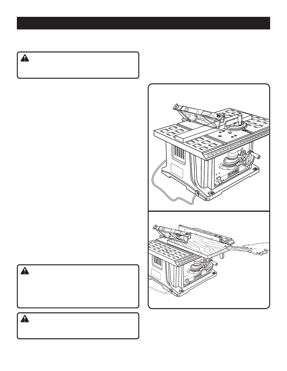
Fig. 29
Fig. 30
BEVEL CROSS CUT
BEVEL RIP CUT
TO MAKE A BEVEL CROSS CUT
See Figure 29.
WARNING:
Make sure the blade guard assembly is installed and
working properly to avoid serious personal injury.
Remove the rip fence by depressing the lock and lifting
the locking handle.
Turn the bevel locking lever to the left to unlock it. Turn
the blade adjusting handle until the bevel indicator is at
the desired angle.
Set the blade to the correct depth for the workpiece and
retighten the bevel locking lever.
Set the miter gauge at 90° and tighten the miter gauge
lock knob.
Place a support (the same height as saw table) behind
the saw for the cut work.
Make sure the wood is clear of the blade before turning
on the saw.
Turn the saw
ON.
Let the saw blade build up to full speed before moving
the workpiece into the blade.
Hold the workpiece firmly with both hands on the miter
gauge and feed the workpiece into the blade. Keep the
workpiece flush against the miter gauge. Stand slightly
to the side of the wood as it contacts the blade to reduce
the chance of injury should kickback occur.
NOTE: The hand closest to the blade should be placed
on the miter gauge lock knob and the hand farthest from
the blade should be placed on the workpiece.
When the cut is made, turn the saw
OFF. Wait for the
blade to come to a complete stop before removing any
part of the workpiece.
TO MAKE A BEVEL RIP CUT
See Figure 30.
WARNING:
When making a bevel rip cut, the rip fence must be on
the right side of the blade to avoid trapping the wood and
causing kickback. Placement of the rip fence to the left
of the blade will result in kickback and the risk of serious
personal injury.
WARNING:
Make sure the blade guard assembly is installed and
working properly to avoid serious personal injury.
Remove the miter gauge by sliding it out of the miter
gauge groove.
Turn the bevel locking lever to the left to unlock. Turn the
blade adjusting handle until the bevel indicator is at the
desired angle.
Set the blade to the correct depth for the workpiece and
push the bevel locking lever to the right to relock it.