Adjustments – Ryobi BTS10S User Manual
Page 31
31
ADJUSTMENTS
TO SET THE 90° POSITIVE STOP
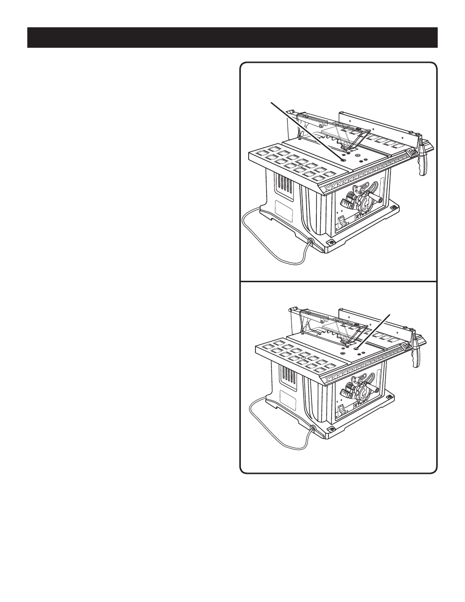
See Figure 34.
Make sure the saw is unplugged from the power source.
Raise the blade to the maximum height by turning the
blade adjusting handle counterclockwise. Unlock the bevel
locking lever.
Next, push the blade adjusting handle in toward the saw
and rotate clockwise until it stops. Use the framing square
to check the position of the blade. Relock the bevel locking
lever.
If the blade angle is less than 90°, turn the 90° positive
stop adjustment screw counterclockwise one turn. Push the
blade adjusting handle in and rotate counterclockwise until
it stops. Recheck the blade position. Continue this process
until the blade is at 90°. Relock the bevel locking lever.
If the blade angle is greater than 90°, use the framing
square to position the blade to 90°. Turn the 90° positive
stop adjustment screw clockwise until it stops. Relock the
bevel locking lever.
Reset the bevel indicator to 0° by loosening the screw
holding the indicator. Line up the red line on the indicator
with the 0° mark on the bevel scale.
TO SET THE 45° POSITIVE STOP
See Figure 35.
Make sure the saw is unplugged from the power source.
Raise the blade to the maximum height by turning the blade
adjusting handle counterclockwise. Turn the bevel locking
lever to the left to loosen the bevel.
Next, push the blade adjusting handle in and rotate counter-
clockwise until it stops. Check the blade position using the
angled corner of a combination square or triangle.
If the blade angle is greater than 45°, turn the 45° positive
stop adjustment screw counterclockwise 1 turn and rotate
the bevel adjusting handle counterclockwise until it stops.
Recheck the blade position. Continue this process until the
blade is at 45°. Tighten the bevel locking lever.
If the blade angle is less than 45°, use the combination
square or triangle to position the blade at 45°. Turn the 45°
positive stop adjustment screw clockwise until it stops.
Tighten the bevel locking lever.
Reset the bevel indicator to 45° by loosening the screw
holding the indicator. Line up the red line on the indicator
with the 45° mark on the bevel scale.
Fig. 34
90° POSITIVE
STOP
ADJUSTMENT
SCREW
Fig. 35
45° POSITIVE
STOP
ADJUSTMENT
SCREW