Warning, Caution – Nexen TL60-A 951243 User Manual
Page 13
13
FORM NO. L-20138-U-0912
PARTS REPLACEMENT
1. Shut off machine and air supply to the Torque
Limiter.
2. Disconnect the Torque Limiter from the air supply by
removing the Quick Exhaust Shuttle Valve and the
3-Way N.C. Solenoid Valve.
3. Remove the Torque Limiter from the machine.
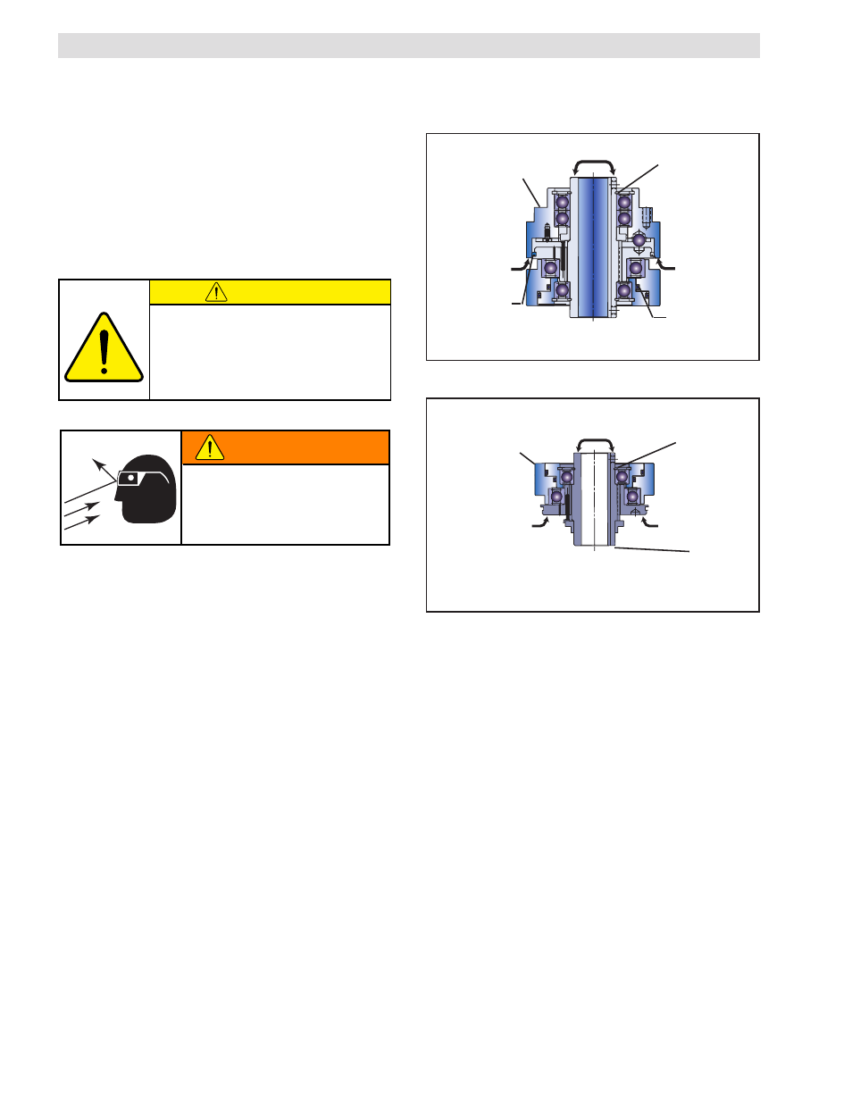
Drive Flange
Assembly
(Item 19)
Cylinder/Piston
Assembly
(Items 8 and 9)
FIGURE 13
Rotary Seal
(Item 15)
Retaining Ring
(Item 6)
Press
Support
Support
4. Remove the Retaining Ring (Item 6) from the Hub
(Item 7) on the Drive Flange Assembly (Item 19) end
of the Torque Limiter (See Figure 13).
5. Supporting Drive Flange Assembly (Item 19), press
Hub (Item 7) and Cylinder/Piston Assembly out of
Drive Flange (See Figure 13).
6. Remove the Rotary Seal (Item 15) from the
Cylinder/Piston Assembly (Items 8 and 9) (See
Figure 13).
7. Remove Retaining Ring (Item 6) from Hub (Item
7) on Cylinder/Piston end of Torque Limiter (See
Figure 14).
8. Supporting Cylinder/Piston Assembly, press Hub
(Item 7) out of Cylinder/Piston Assembly (See
Figure 14).
Cylinder/Piston
Assembly
(Items 8 and 9)
Hub
(Item 7)
FIGURE 14
Retaining Ring
(Item 6)
Support
Press
Support
TORQUE LIMITER REMOVAL AND DISASSEMBLY
CAUTION
Correct alignment of Torque Limiter internal
components is critical for proper operation
of the Torque Limiter. Before disassembly,
mark Hub, Cylinder, and Drive Flange with
chalk alignment marks to ensure correct
alignment of internal components when
reassembling Torque Limiter.
WARNING
Special attention should be exercised
when working with retaining rings.
Always wear safety goggles when
working with spring or tension loaded
fasteners or devices.
- TL60-A 951296 TL60-A 951242 TL60-A 951244 TL20-A 951203 TL20-A 951292 TL20-A 951202 TL20-A 951210 TL10-A 951302 TL30-A 951213 TL30-A 951212 TL30-A 951294 TL30-A 951298 TL30-A 951214 TL15-A 951312 TL40-A 951223 TL40-A 951293 TL40-A 951222 TL40-A 951281 TL40-A 951301 TL50-A 951233 TL50-A 951295 TL50-A 951232 TL40-AC/2 801842 TL40-AC/2 801524 TL60-AC 801540 TL80-AC/2 801564 TL70-AC 801550 TL30-AC 801863 TL30-AC 801510 TL30-AC4P 801915 TL30-AC6P 801916 TL30-AC 801589 TL50-AC/2 801534 TL80-AC 801560 TL60-AC/2 801544 TL40-AC 801822 TL40-AC 801884 TL40-AC 801876 TL40-AC 801591 TL40-AC 801520 TL20-AC/2 801504 TL50-AC 801828 TL50-AC 801530 TL70-AC/2 801554 TL30-AC/2 801514 TL20-AC 801587 TL20-AC 801500 TL40-A/2 801526 TL60-A 801870 TL60-A 801805 TL60-A 801542 TL20-A 951204 TL80-A/2 801566 TL70-A 801674 TL70-A 801552 TL10-A 801802 TL10-A 801905 TL30-A 801593 TL30-A-4P 801875 TL30-A 801512 TL30-A 801821 TL30-A 801592 TL50-A/2 801920 TL50-A/2 801536 TL80-A 801833 TL80-A 801925 TL80-A 801825 TL80-A 801562 TL60-A/2 801546 TL60-A/2 802950 TL15-A 801812 TL15-A 801816 TL40-A 951221 TL40-A 801588 TL40-A 801845 TL40-A 801584 TL40-A 801522 TL20-A/2 801811 TL20-A/2 801506 TL20-A/2 801881 TL50-A 801595 TL50-A 801865 TL50-A 801596 TL50-A 801532 TL70-A/2 801556 TL30-A/2 801878 TL30-A/2 801516 TL30-A/2 801924 TL20-A 801599 TL20-A 801502 TL20-A 801851 TL20A 801508 TL30A 801518 TL40A 801528 TL50A 801538 TL60A 801548 TL70A 801558 TL70A-E 801568 TL-10 801808 TL-15 801808