Warning, Caution – Nexen TL60-A 951243 User Manual
Page 6
6
FORM NO. L-20138-U-0912
TORQUE LIMITER ASSEMBLY
Hub
(Item 7)
Drive Flange
Assembly
(Item 19)
Retaining
Ring (Item 6)
FIGURE 2
Ball Bearing
(Item 21)
Torque Limiter
Hub
Rotary
Seal
(Item 15)
Retaining Ring
(Item 6)
Cylinder/Piston
Assembly
FIGURE 5
Ball Bearing
(Item 21)
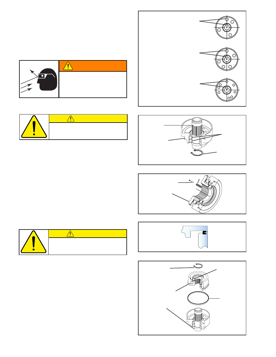
Align this ball detent
with Hub keyway on
TL20 through TL60.
FIGURE 1
Align this ball detent
with Hub keyway on
TL10 and TL15.
Align this ball detent
with Hub keyway on
TL70 and TL80.
NOTE: When assembling the Torque Limiter, align the
Hub keyway with balls as shown ( See Figure 1).
1. While fully supporting the two Ball Bearings (Item
21), press the Hub (Item 7) into the Drive Flange
Assembly (Item 19) (See Figure 2).
2. Install the Retaining Ring (Item 6) (See Figure 2).
3. Lubricate the Drive Flange Assembly (Item 19) (See
LUBRICATION).
4. Install the Compression Springs (Items 17) and
Spring Stiffener Pins (Item 16) into the Drive Ring
(Item 10) (See Figure 3).
NOTE: The back of the Rotary Seal must be installed
facing the Drive Flange Assembly end of Torque
Limiter (See Figure 4).
5. Install the Rotary Seal (Item 15) (See Figures 4 and
5).
6. Lubricate the Hub spline with NEVER-SEEZ
®
.
7. While fully supporting the inner race of the Ball
Bearing (Item 21), press the Cylinder/Piston
Assembly onto the Hub of the Torque Limiter (See
Figure 5).
8. Install Retaining Ring (Item 6) (See Figure 5).
16
10
17
FIGURE 3
FIGURE 4
Drive Flange
Drive Ring
WARNING
Special attention should be exercised
when working with retaining rings.
Always wear safety goggles when
working with spring or tension loaded
fasteners or devices.
CAUTION
Do not over-lubricate the Drive Flange Assembly.
Over-lubricating creates a hydraulic effect within
the Torque Limiter which will adversely affect the
break-away torque.
CAUTION
Care must be exercised when sliding the Cylinder/
Piston Assembly onto Hub and into Drive Flange
Assembly to avoid damage to the Rotary Seal.
- TL60-A 951296 TL60-A 951242 TL60-A 951244 TL20-A 951203 TL20-A 951292 TL20-A 951202 TL20-A 951210 TL10-A 951302 TL30-A 951213 TL30-A 951212 TL30-A 951294 TL30-A 951298 TL30-A 951214 TL15-A 951312 TL40-A 951223 TL40-A 951293 TL40-A 951222 TL40-A 951281 TL40-A 951301 TL50-A 951233 TL50-A 951295 TL50-A 951232 TL40-AC/2 801842 TL40-AC/2 801524 TL60-AC 801540 TL80-AC/2 801564 TL70-AC 801550 TL30-AC 801863 TL30-AC 801510 TL30-AC4P 801915 TL30-AC6P 801916 TL30-AC 801589 TL50-AC/2 801534 TL80-AC 801560 TL60-AC/2 801544 TL40-AC 801822 TL40-AC 801884 TL40-AC 801876 TL40-AC 801591 TL40-AC 801520 TL20-AC/2 801504 TL50-AC 801828 TL50-AC 801530 TL70-AC/2 801554 TL30-AC/2 801514 TL20-AC 801587 TL20-AC 801500 TL40-A/2 801526 TL60-A 801870 TL60-A 801805 TL60-A 801542 TL20-A 951204 TL80-A/2 801566 TL70-A 801674 TL70-A 801552 TL10-A 801802 TL10-A 801905 TL30-A 801593 TL30-A-4P 801875 TL30-A 801512 TL30-A 801821 TL30-A 801592 TL50-A/2 801920 TL50-A/2 801536 TL80-A 801833 TL80-A 801925 TL80-A 801825 TL80-A 801562 TL60-A/2 801546 TL60-A/2 802950 TL15-A 801812 TL15-A 801816 TL40-A 951221 TL40-A 801588 TL40-A 801845 TL40-A 801584 TL40-A 801522 TL20-A/2 801811 TL20-A/2 801506 TL20-A/2 801881 TL50-A 801595 TL50-A 801865 TL50-A 801596 TL50-A 801532 TL70-A/2 801556 TL30-A/2 801878 TL30-A/2 801516 TL30-A/2 801924 TL20-A 801599 TL20-A 801502 TL20-A 801851 TL20A 801508 TL30A 801518 TL40A 801528 TL50A 801538 TL60A 801548 TL70A 801558 TL70A-E 801568 TL-10 801808 TL-15 801808