Introduction hub preparation – Nexen TL60-A 951243 User Manual
Page 5
5
FORM NO. L-20138-U-0912
INTRODUCTION
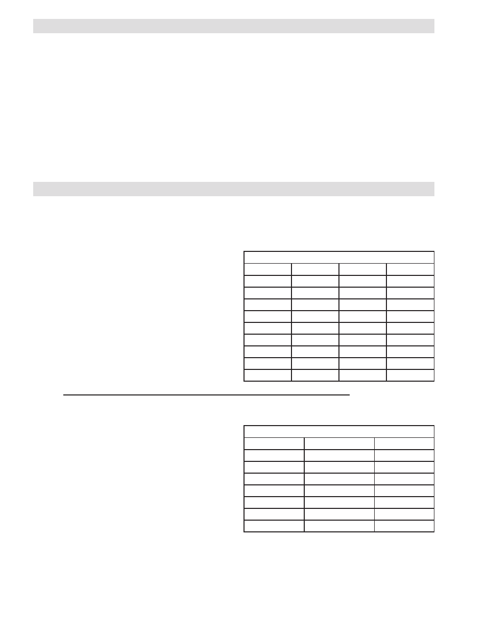
HUB PREPARATION
NOTE: This section pertains only to units with a customer machined bore. If your Torque Limiter has been
bored by Nexen, proceed with INSTALLATION.
TL-A
After the Hub has been finished bored, drill and tap the
Hub for Set Screws. Set Screw locations are over the
keyway, and at 90
o
of the keyway. Models TL10-A and
TL15-A require two Set Screws located on the Drive
Flange end of the Hub. Models TL20-A and higher
require two Set Screws located on both ends of the
Hub (Refer to Table 1 for Set Screw sizes).
TL-AC
After the Hub has been finished bored, make four saw
cuts in the Drive Flange end of the Hub. Locate the first
saw cut 45
o
from the keyway and the other three saw
cuts at 90
o
increments from the first saw cut (Refer to
Table 2 for saw cut dimensions).
TABLE 1
TABLE 2
Nexen's air-engaged, single-position Torque Limiters provide overload protection for power transmission equipment,
thus protecting machinery and product from jam-ups and resultant down time expense.
The totally enclosed construction of Nexen's Enclosed Torque Limiter allows for usage in wet or humid conditions and
is acceptable for use in federally inspected meat and poultry plants.
A Proximity Sensor (located on the Torque Limiter) senses the onset of an overload condition and releases air pressure
at the 3-way valve to provide split second disengagement of the Torque Limiter.
The single position feature resets in the same position when the unit is engaged, providing exact timing of two
components.
SET SCREW SIZES
MODEL
US
METRIC
QTY
TL10-A10
10-24
M5-0.8
2
TL15-A
10-24
M5-0.8
2
TL20-A
1/4-20
M6-1.0
4
TL30-A
5/16-24
M6-1.0
4
TL40-A
3/8-24
M10-1.5
4
TL50-A
3/8-24
M10-1.5
4
TL60-A
1/2-13
M12-1.75
4
TL70-A
1/2-13
M12-1.75
4
TL80-A
1/2-13
M12-1.75
4
SAW CUT DIMENSIONS
MODEL
CUT WIDTH
CUT DEPTH
TL20-AC
0.06" [1.52 mm]
0.96" [25.4 mm]
TL30-AC
0.06" [1.52 mm]
0.96" [25.4 mm]
TL40-AC
0.06" [1.52 mm]
0.96" [25.4 mm]
TL50-AC
0.06" [1.52 mm]
0.96" [25.4 mm]
TL60-AC
0.06" [1.52 mm]
0.96" [25.4 mm]
TL70-AC
0.06" [1.52 mm]
0.96" [25.4 mm]
TL80-AC
0.06" [1.52 mm]
0.96" [25.4 mm]
- TL60-A 951296 TL60-A 951242 TL60-A 951244 TL20-A 951203 TL20-A 951292 TL20-A 951202 TL20-A 951210 TL10-A 951302 TL30-A 951213 TL30-A 951212 TL30-A 951294 TL30-A 951298 TL30-A 951214 TL15-A 951312 TL40-A 951223 TL40-A 951293 TL40-A 951222 TL40-A 951281 TL40-A 951301 TL50-A 951233 TL50-A 951295 TL50-A 951232 TL40-AC/2 801842 TL40-AC/2 801524 TL60-AC 801540 TL80-AC/2 801564 TL70-AC 801550 TL30-AC 801863 TL30-AC 801510 TL30-AC4P 801915 TL30-AC6P 801916 TL30-AC 801589 TL50-AC/2 801534 TL80-AC 801560 TL60-AC/2 801544 TL40-AC 801822 TL40-AC 801884 TL40-AC 801876 TL40-AC 801591 TL40-AC 801520 TL20-AC/2 801504 TL50-AC 801828 TL50-AC 801530 TL70-AC/2 801554 TL30-AC/2 801514 TL20-AC 801587 TL20-AC 801500 TL40-A/2 801526 TL60-A 801870 TL60-A 801805 TL60-A 801542 TL20-A 951204 TL80-A/2 801566 TL70-A 801674 TL70-A 801552 TL10-A 801802 TL10-A 801905 TL30-A 801593 TL30-A-4P 801875 TL30-A 801512 TL30-A 801821 TL30-A 801592 TL50-A/2 801920 TL50-A/2 801536 TL80-A 801833 TL80-A 801925 TL80-A 801825 TL80-A 801562 TL60-A/2 801546 TL60-A/2 802950 TL15-A 801812 TL15-A 801816 TL40-A 951221 TL40-A 801588 TL40-A 801845 TL40-A 801584 TL40-A 801522 TL20-A/2 801811 TL20-A/2 801506 TL20-A/2 801881 TL50-A 801595 TL50-A 801865 TL50-A 801596 TL50-A 801532 TL70-A/2 801556 TL30-A/2 801878 TL30-A/2 801516 TL30-A/2 801924 TL20-A 801599 TL20-A 801502 TL20-A 801851 TL20A 801508 TL30A 801518 TL40A 801528 TL50A 801538 TL60A 801548 TL70A 801558 TL70A-E 801568 TL-10 801808 TL-15 801808