Installation – Nexen TL60-A 951243 User Manual
Page 7
7
FORM NO. L-20138-U-0912
INSTALLATION
TORQUE LIMITER
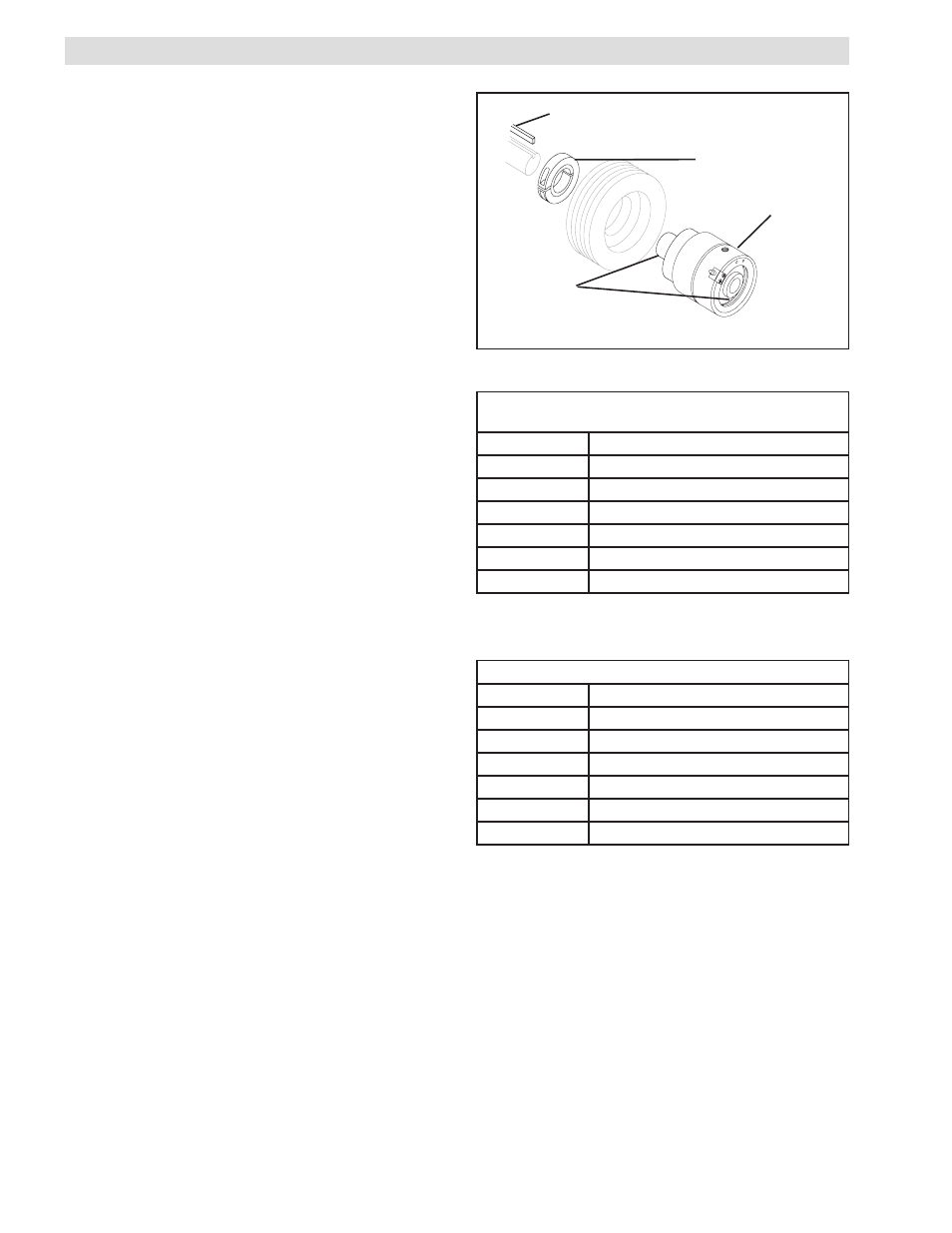
1. Using customer supplied cap screws, fasten a
sheave or sprocket to the Torque Limiter (See
Figure 6).
NOTE: Nexen recommends using a red anaerobic
thread locking compound on pilot mounting holes.
2. Slide the Clamping Collar (Item 1 Model TL-AC)
onto the Hub of the Torque Limiter (See Figure 6).
3. Insert a customer supplied key into the shaft
keyway.
4. Align the keyway of the Torque Limiter with the shaft
and key; then, slide the Torque Limiter onto the shaft
(See Figure 6).
5. Tighten the Clamping Collar (Item 1 Model TL-
AC) or Set Screws (Item 1 Model TL-A) to the
recommended torque (See Tables 3 and 4).
Customer supplied key
Torque
Limiter
Locking Collar
(Item 1 Model
TL-AC)
Set Screws
(Item 1 Model
TL-A)
FIGURE 6
TABLE 3
TABLE 4
SET SCREW TORQUE SPECIFICATIONS
TL20-A
7 Ft. Lbs. [9.5 Nm]
TL30-A
14 Ft. Lbs. [19 Nm]
TL40-A
24 Ft. Lbs. [32.5 Nm]
TL50-A
24 Ft. Lbs. [32.5 Nm]
TL60-A
51 Ft. Lbs. [69 Nm]
TL70-A
51 Ft. Lbs. [69 Nm]
TL80-A
51 Ft. Lbs. [69 Nm]
CLAMPING COLLAR SCREW TORQUE
SPECIFICATIONS
TL20-A
15 Ft. Lbs. [20.3 Nm]
TL30-A
33 Ft. Lbs. [44.7 Nm]
TL40-A
33 Ft. Lbs. [44.7 Nm]
TL50-A
58 Ft. Lbs. [78.4 Nm]
TL60-A
58 Ft. Lbs. [78.4 Nm]
TL70-A
58 Ft. Lbs. [78.4 Nm]
TL80-A
58 Ft. Lbs. [78.4 Nm]
- TL60-A 951296 TL60-A 951242 TL60-A 951244 TL20-A 951203 TL20-A 951292 TL20-A 951202 TL20-A 951210 TL10-A 951302 TL30-A 951213 TL30-A 951212 TL30-A 951294 TL30-A 951298 TL30-A 951214 TL15-A 951312 TL40-A 951223 TL40-A 951293 TL40-A 951222 TL40-A 951281 TL40-A 951301 TL50-A 951233 TL50-A 951295 TL50-A 951232 TL40-AC/2 801842 TL40-AC/2 801524 TL60-AC 801540 TL80-AC/2 801564 TL70-AC 801550 TL30-AC 801863 TL30-AC 801510 TL30-AC4P 801915 TL30-AC6P 801916 TL30-AC 801589 TL50-AC/2 801534 TL80-AC 801560 TL60-AC/2 801544 TL40-AC 801822 TL40-AC 801884 TL40-AC 801876 TL40-AC 801591 TL40-AC 801520 TL20-AC/2 801504 TL50-AC 801828 TL50-AC 801530 TL70-AC/2 801554 TL30-AC/2 801514 TL20-AC 801587 TL20-AC 801500 TL40-A/2 801526 TL60-A 801870 TL60-A 801805 TL60-A 801542 TL20-A 951204 TL80-A/2 801566 TL70-A 801674 TL70-A 801552 TL10-A 801802 TL10-A 801905 TL30-A 801593 TL30-A-4P 801875 TL30-A 801512 TL30-A 801821 TL30-A 801592 TL50-A/2 801920 TL50-A/2 801536 TL80-A 801833 TL80-A 801925 TL80-A 801825 TL80-A 801562 TL60-A/2 801546 TL60-A/2 802950 TL15-A 801812 TL15-A 801816 TL40-A 951221 TL40-A 801588 TL40-A 801845 TL40-A 801584 TL40-A 801522 TL20-A/2 801811 TL20-A/2 801506 TL20-A/2 801881 TL50-A 801595 TL50-A 801865 TL50-A 801596 TL50-A 801532 TL70-A/2 801556 TL30-A/2 801878 TL30-A/2 801516 TL30-A/2 801924 TL20-A 801599 TL20-A 801502 TL20-A 801851 TL20A 801508 TL30A 801518 TL40A 801528 TL50A 801538 TL60A 801548 TL70A 801558 TL70A-E 801568 TL-10 801808 TL-15 801808