Disassembly—pilot, coupling, and sheave mount – Nexen MWCB 830812 User Manual
Page 12
12
FORM NO. L-20016-X-1209
LWCB AND MWCB
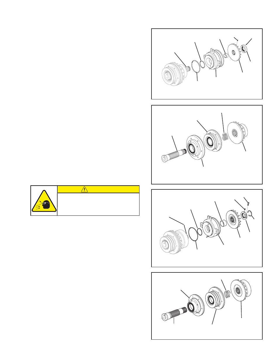
Refer to Figures 9 & 10.
1. Loosen the Set Screws (Items 28 and 29); then, remove the
Locking Nut (Item 26) and the Brake Friction Disc (Item 2).
2. Remove the Spacer (Item 16).
3. Press the Brake Assembly off the Hub (Item 1).
4. Remove the O-Ring Seals (Items 19 and 21).
5. Slide the Clutch Assembly off the Hub (Item 1).
6. Slide the Compression Spring (Item 11) off the Hub (Item
1).
7. Press the Drive Disc Assembly or the Sheave Assembly off
the Hub (Item 1).
HWCB
Refer to Figures 11 & 12.
1. Remove the Retaining Ring (Item 45) from the Clutch-
Brake.
2. Loosen the Set Screw (Item 28) and the Socket Head Cap
Screw (Item 47) securing the Locking Collar (Item 46); then,
remove the Locking Collar (Item 46) and the Brake Friction
Disc (Item 44).
3. Remove the Spacer (Item 16).
4. Press the Brake Assembly off the Hub (Item 43).
5. Remove the O-Ring Seals (Items 19 and 21).
6. Slide the Clutch Assembly off the Hub (Item 43).
7. Slide the Compression Spring (Item 11) off the Hub (Item
43).
8. Press the Drive Disc Assembly or the Sheave Assembly off
the Hub (Item 43).
FIGURE 9
Hub
(Item 1)
19
21
Brake
Assembly
16
2
26
28
29
FIGURE 10
Clutch
Assembly
Sheave
Assembly
Drive Disc
Assembly
1
11
FIGURE 11
Hub
(Item 43)
19
21
Brake
Assembly
16
44
46
45
28
47
FIGURE 12
43
Drive Disc
Assembly
Sheave
Assembly
Clutch
Assembly
11
CAUTION
Working with spring loaded or tension
loaded fasteners and devices can cause
injury. Wear safety glasses and take the
appropriate safety precautions.
DISASSEMBLy—PILOT, COUPLING, AND SHEAVE MOUNT
(continued)
- HWCB 832501 HWCB 832913 HWCB 832401 HWCB 832600 HWCB 832400 HWCB 832500 HWCB 832700 HWCB 832800 HWCB 832900 HWCB 832941 HWCB 832902 LWCB 828901 HWCB 832907 FWCB 827111 FWCB 826700 FWCB 826800 FWCB 826900 FWCB 827000 FWCB 827100 LWCB 828300 LWCB 828400 LWCB 828500 LWCB 828600 LWCB 828700 LWCB 828800 LWCB 828900 LWCB 828942 LWCB 828904 MWCB 830603 MWCB 830801 MWCB 830601 FWCB 827101 LWCB 828301 LWCB 828907 MWCB 830602 MWCB 830301 MWCB 830811 MWCB 830600 MWCB 830700 MWCB 830300 MWCB 830400 MWCB 830500 MWCB 830800 MWCB 830841 MWCB 830803 MWCB 830802 FWCB 847801 MWCB 848001 LWCB 847901 LWCB 847907 MWCB 848002 HWCB 848102 HWCB 848100 FWCB 847800 LWCB 847900 MWCB 848000