Nexen MWCB 830812 User Manual
Page 20
20
FORM NO. L-20016-X-1209
HWCB
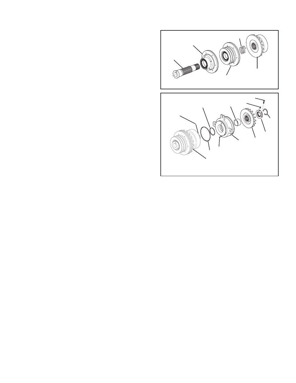
Refer to Figures 31 & 32.
1. Fully supporting the inner bearing race, press the Hub (Item
43) into the Sheave of Drive Disc Assembly.
2. Slide the Compression Spring (Item 11) onto the Hub (Item
43); then, supporting the inner bearing race, press the Clutch
Assembly onto the Hub (Item 43).
3. Lubricate the new O-Ring Seals (Items 19 and 21) with fresh
O-Ring lubricant; then, install the new O-Rings Seals onto
the Brake and Clutch Assemblies.
4. Align the Slotted Spring Pin (Item 23) located on the Brake
Assembly with the hole in the Clutch Assembly and press
the Brake Assembly onto the Hub (Item 43).
5. Slide the Spacer (Item 16) onto the Hub (Item 43); then,
slide the Brake Friction Disc (Item 44) onto the Hub.
6. Align the two holes in the Locking Collar (Item 46) with the
two holes in the Hub (Item 43); then, reinstall the Locking
Collar and tighten the Socket Head Cap Screw (Item 47) to
300 In. Lbs. [33.6 Nm] torque.
FIGURE 31
43
Drive Disc
Assembly
Sheave
Assembly
Clutch
Assembly
11
FIGURE 32
Hub
(Item 43)
19
21
Brake
Assembly
16
44
46
45
28
47
23
Clutch
Assembly
REASSEMBLy—PILOT, COUPLING, AND SHEAVE MOUNT (continued)
- HWCB 832501 HWCB 832913 HWCB 832401 HWCB 832600 HWCB 832400 HWCB 832500 HWCB 832700 HWCB 832800 HWCB 832900 HWCB 832941 HWCB 832902 LWCB 828901 HWCB 832907 FWCB 827111 FWCB 826700 FWCB 826800 FWCB 826900 FWCB 827000 FWCB 827100 LWCB 828300 LWCB 828400 LWCB 828500 LWCB 828600 LWCB 828700 LWCB 828800 LWCB 828900 LWCB 828942 LWCB 828904 MWCB 830603 MWCB 830801 MWCB 830601 FWCB 827101 LWCB 828301 LWCB 828907 MWCB 830602 MWCB 830301 MWCB 830811 MWCB 830600 MWCB 830700 MWCB 830300 MWCB 830400 MWCB 830500 MWCB 830800 MWCB 830841 MWCB 830803 MWCB 830802 FWCB 847801 MWCB 848001 LWCB 847901 LWCB 847907 MWCB 848002 HWCB 848102 HWCB 848100 FWCB 847800 LWCB 847900 MWCB 848000