Installation, Lubrication, Sheave mount clutch-brake – Nexen MWCB 830812 User Manual
Page 7: Caution
7
FORM NO. L-20016-X-1209
NOTE
Nexen pneumatically actuated devices require clean, pressure regulated air for maximum performance and
life. All seals in Nexen pneumatically operated devices are lubricated for life, and do not require additional
lubrication.
However, some customers prefer to use an air line lubricator, which injects oil into the pressurized air, forcing
an oil mist into the air chamber. This is acceptable, but care must be taken to ensure once an air mist lubrication
system is used, it is continually used over the life of the product as the oil mist may wash free the factory
installed lubrication.
Locate the lubricator above and within ten feet of the product, and use low viscosity oil such as SAE-10.
Synthetic lubricants are not recommended.
Nexen product's bearings are shielded and pre-lubricated, and require no further lubrication.
LUBRICATOR DRIP RATE SETTINGS
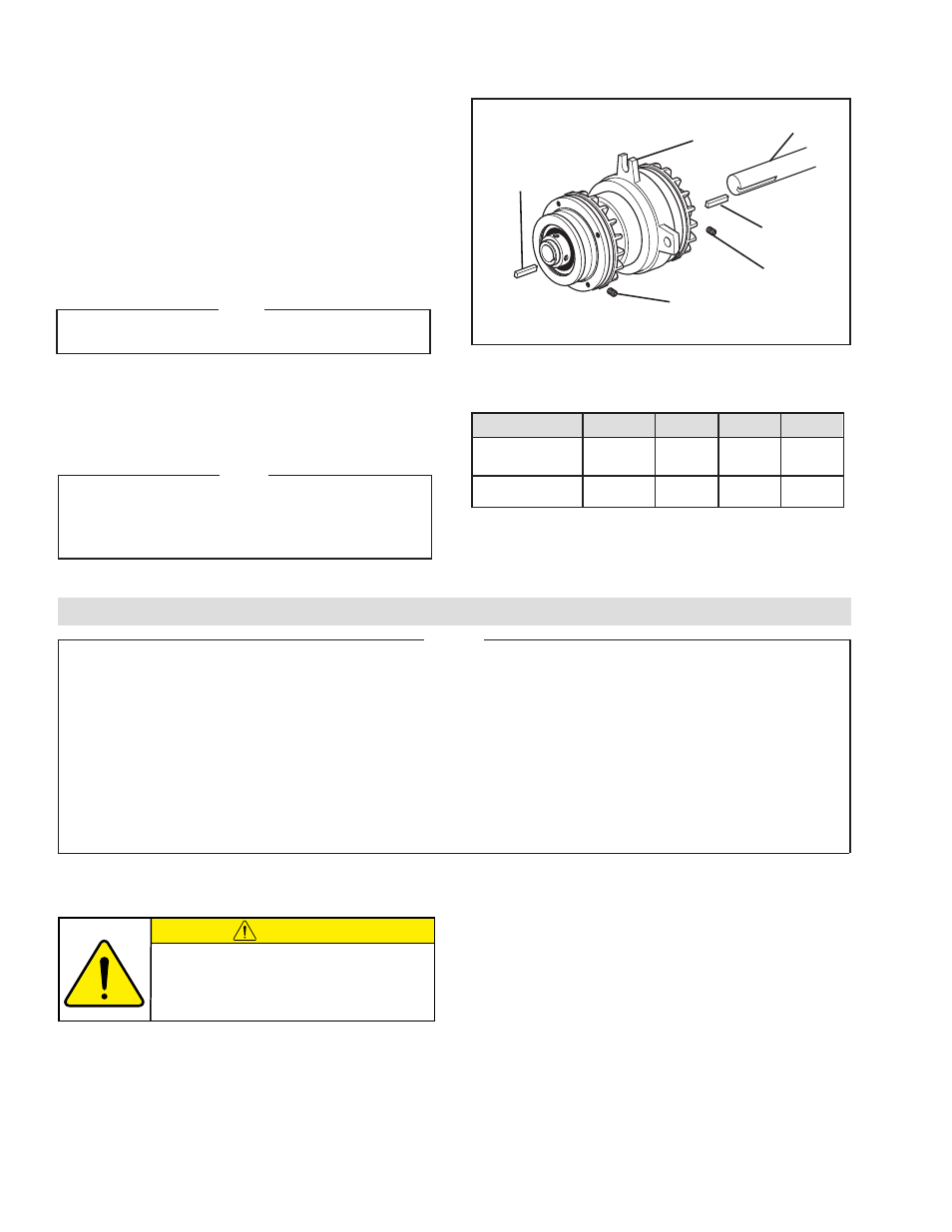
SHEAVE MOUNT CLUTCH-BRAKE
Refer to Figure 3.
1. Insert the first Key (Item 30) into the shaft.
2. Slide the Clutch-Brake onto shaft and key; then, insert the
second Key (Item 30).
3. Tighten Set Screws (Items 27 and 28) to the recommended
torque (See Table 4).
NOTE
If a bushing for smaller diameter shafts is required, use
a bushing on both ends of the Clutch-Brake.
4. Align air inlet ports to a six o’clock down position to allow
condensation to drain out of exhaust port.
5. Fasten one of the ears of the Clutch-Brake to a fixed member
of the machine.
NOTE
The Piston Air Chamber (Item 7) floats laterally approxi-
mately 1/16 inch [1.59 mm] during operation. Make sure
securing pin allows 1/16 inch to 1/8 inch [1.59 mm to 3.18
mm] movement of Piston Air Chamber.
FIGURE 3
Shaft
Key
(Item 30)
Set Screw
(Item 28
or 48)
Set Screw
(Item 27)
Key
(Item 30)
Clutch-Brake
TABLE 4
RECOMMENDED TIGHTENING TORQUES
INSTALLATION
(continued)
DESCRIPTION
FWCB
LWCB
MWCB
HWCB
35 In. Lbs.
80 In. Lbs. 80 In. Lbs. 23 Ft. Lbs.
Set Screw (Item 27)
[3.9 N•m]
[8.9 N•m]
[8.9 N•m] [31.2 N•m]
20 In. Lbs.
20 In. Lbs. 80 In. Lbs.
— —
Set Screw (Item 28)
[2.2 N•m]
[2.2 N•m]
[8.9 N•m]
— —
1. Close and disconnect the air line from the unit.
2. Turn the Lubricator Adjustment Knob counterclockwise
three complete turns.
3. Open the air line.
LUBRICATION
CAUTION
These settings are for Nexen supplied
lubricators. If you are not using a Nexen
lubricator, calibration must follow the
manufacturer's suggested procedure.
4. Close the air line to the unit when a drop of oil forms
in the Lubricator Sight Gage.
5. Connect the air line to the unit.
6. Turn the Lubricator Adjustment Knob clockwise until
closed.
7. Turn the Lubricator Adjustment Knob counterclockwise
one-third turn.
8. Open the air line to the unit.
- HWCB 832501 HWCB 832913 HWCB 832401 HWCB 832600 HWCB 832400 HWCB 832500 HWCB 832700 HWCB 832800 HWCB 832900 HWCB 832941 HWCB 832902 LWCB 828901 HWCB 832907 FWCB 827111 FWCB 826700 FWCB 826800 FWCB 826900 FWCB 827000 FWCB 827100 LWCB 828300 LWCB 828400 LWCB 828500 LWCB 828600 LWCB 828700 LWCB 828800 LWCB 828900 LWCB 828942 LWCB 828904 MWCB 830603 MWCB 830801 MWCB 830601 FWCB 827101 LWCB 828301 LWCB 828907 MWCB 830602 MWCB 830301 MWCB 830811 MWCB 830600 MWCB 830700 MWCB 830300 MWCB 830400 MWCB 830500 MWCB 830800 MWCB 830841 MWCB 830803 MWCB 830802 FWCB 847801 MWCB 848001 LWCB 847901 LWCB 847907 MWCB 848002 HWCB 848102 HWCB 848100 FWCB 847800 LWCB 847900 MWCB 848000