Nexen MWCB 830812 User Manual
Page 16
16
FORM NO. L-20016-X-1209
NOTE
If the Ball Bearing (Item 14) comes out of the Air Chamber
(Item 8), use a bearing puller to remove it from the Clutch
Friction Disc (Item 9). If the Ball Bearing remains in the
Air Chamber (Item 8), use a die remover to remove it from
the Air Chamber.
11. Clean the bearing bore of the Air Chamber (Item 8) with
fresh safety solvent, making sure all old Loctite
®
residue is
removed.
12. Apply an adequate amount of Loctite
®
680 to evenly coat
the outer race of the new Ball Bearing (Item 14).
13. Carefully align the O.D. of the new Ball Bearing (Item 14)
with the bore of the Air Chamber (Item 8) and press the new
Ball Bearing into place.
14. Carefully align the hub of the Clutch Friction Disc (Item 9)
with the bore of the new Ball Bearing (Item 14) and press
the Clutch Friction Disc into the new Ball Bearing and Air
Chamber (Item 8).
15. Remove the old Flat Head Machine Screws (Item 24) and
Friction Facing (Item 4) from the Piston (Item 3).
16. Remove the Shoulder Bolts (Item 5), Shoulder Bolt O-Rings
(Item 22), and Compression Springs (Item 6).
17. Separate the Piston Air Chamber (Item 7) and Piston (Item
3).
18. Remove the old O-Ring Seals (Items 18 and 20) from the
Piston Air Chamber (Item 7) and Piston (Item 3).
19. Remove the Retaining Ring (Item 17).
20. Press the old Ball Bearing (Item 13) out of the Piston Air
Chamber (Item 7).
21. Clean the bearing bore of the Piston Air Chamber (Item 7)
with fresh safety solvent, making sure all old Loctite
®
residue
is removed.
22. Apply an adequate amount of Loctite
®
680 to evenly coat
the outer race of the new Ball Bearing (Item 13).
23. Carefully align the O.D. of the new Ball Bearing (Item 13)
with the bore of the Piston Air Chamber and press the new
Ball Bearing into place.
24. Reinstall the Retaining Ring (Item 17).
25. Clean all O-Ring grooves and O-Ring contact surfaces with
fresh safety solvent and lubricate the O-Ring grooves and
contact surfaces with fresh O-Ring lubricant.
26. Lubricate the new O-Ring Seals (Items 18, 20, and 22) with
fresh O-Ring lubricant and install the new O-Ring Seals.
27. Press the Piston (Item 3) into the Piston Air Chamber (Item
7).
28. Apply Loctite
®
242 to the threads of the Shoulder Bolts (Item
5); then, install the new Compression Springs (Item 6) and
Shoulder Bolts (Item 5) with new O-Ring Seals (Item 22).
29. Tighten the Shoulder Bolts (Item 5) to 43 In. Lbs. [4.8 Nm]
torque.
30. Install the new Friction Facing (Item 4) and tighten the new
Flat Head Machine Screws (Item 24) to 26 In. Lbs. [2.9 Nm]
torque.
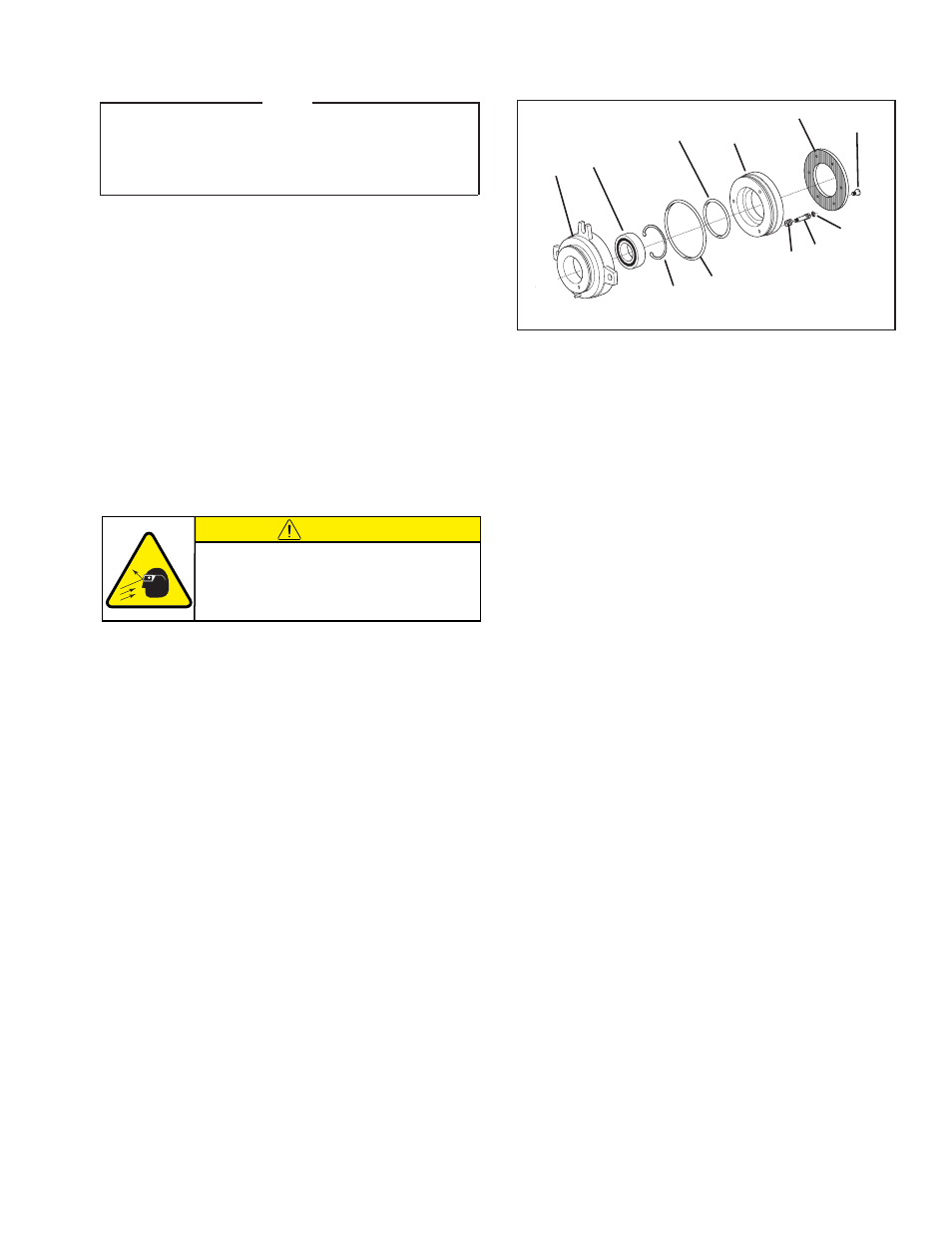
FIGURE 20
7
13
17
18
20
3
6
5
22
4
24
PARTS REPLACEMENT—PILOT, COUPLING, AND SHEAVE MOUNT (continued)
CAUTION
Working with spring loaded or tension
loaded fasteners and devices can cause
injury. Wear safety glasses and take the
appropriate safety precautions.
- HWCB 832501 HWCB 832913 HWCB 832401 HWCB 832600 HWCB 832400 HWCB 832500 HWCB 832700 HWCB 832800 HWCB 832900 HWCB 832941 HWCB 832902 LWCB 828901 HWCB 832907 FWCB 827111 FWCB 826700 FWCB 826800 FWCB 826900 FWCB 827000 FWCB 827100 LWCB 828300 LWCB 828400 LWCB 828500 LWCB 828600 LWCB 828700 LWCB 828800 LWCB 828900 LWCB 828942 LWCB 828904 MWCB 830603 MWCB 830801 MWCB 830601 FWCB 827101 LWCB 828301 LWCB 828907 MWCB 830602 MWCB 830301 MWCB 830811 MWCB 830600 MWCB 830700 MWCB 830300 MWCB 830400 MWCB 830500 MWCB 830800 MWCB 830841 MWCB 830803 MWCB 830802 FWCB 847801 MWCB 848001 LWCB 847901 LWCB 847907 MWCB 848002 HWCB 848102 HWCB 848100 FWCB 847800 LWCB 847900 MWCB 848000