Caution – Nexen MWCB 830812 User Manual
Page 17
17
FORM NO. L-20016-X-1209
HWCB
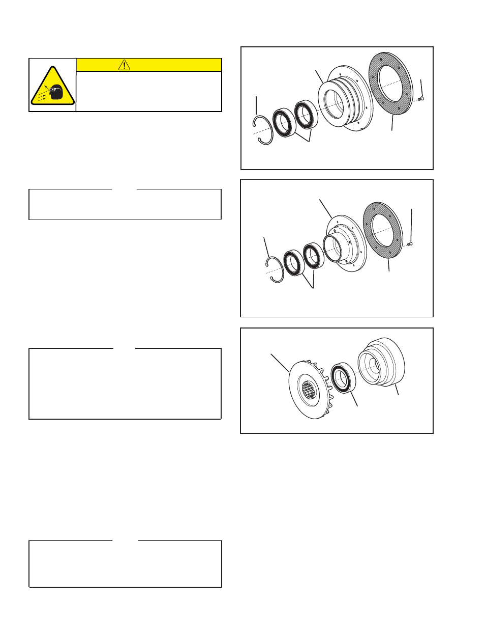
Refer to Figures 21 - 24.
1. Remove the Retaining Ring (Item 41) from the Sheave (Item
12) or Pilot Drive Disc (Item 33).
2. Press the old Ball Bearings (Item 15) out of the Sheave (Item
12) or the Pilot Drive Disc (Item 33).
NOTE
Do not reuse the old ball bearings. Applying force on the
inner race of a ball bearing to remove a ball bearing held
by the outer race causes damage to the bearing.
3. Clean the bearing bore of the Sheave (Item 12) or Pilot Drive
Disc (Item 33) with fresh safety solvent, making sure that all
old Loctite
®
residue is removed.
4. Apply an adequate amount of Loctite
®
680 to evenly coat
the outer race of the new Ball Bearings (Item 15).
5. Support the Sheave (Item 12) or the Pilot Drive Disc (Item
33) and pressing on the outer race of the new Ball Bearings
(Item 15), press the new Ball Bearings (Item 15) into the
Shave or Pilot Drive Disc.
6. Reinstall the Retaining Ring (Item 41)
NOTE
The Flat Head Machine Screws are assembled with an
anaerobic locking compound. Inserting a properly fitting
screwdriver into the head of the Flat Head Machine Screw
and striking the end of the screwdriver with a hammer will
break the crystalline structure of this locking compound
and allow removal of the Flat Head Machine Screws. Never
use an impact wrench to remove the Flat Head Machine
Screws.
7. Remove the old Flat Head Machine Screws (Item 24) securing
the Friction Facing (Item 10) to the Sheave (Item 12) or Pilot
Drive Disc (Item 33).
8. Remove the old Friction Facing (Item 10).
9. Install the new Friction Facing (Item 10) and tighten the new
Flat Head Machine Screws (Item 24) to 43 In. Lbs. [4.8 Nm]
torque.
10. Fully support the Air Chamber (Item 8) and press the Clutch
Friction Disc (Item 9) out of the Air Chamber.
NOTE
If the Ball Bearing (Item 14) comes out of the Air Chamber
(Item 8), use a bearing puller to remove it from the Clutch
Friction Disc (Item 9). If the Ball Bearing remains in the
Air Chamber (Item 8), use a die remover to remove it from
the Air Chamber.
FIGURE 23
9
14
8
FIGURE 22
PILOT MOUNT
41
15
33
10
24
11. Clean the bearing bore of the Air Chamber (Item 8) with
fresh safety solvent, making sure all old Loctite
®
residue is
removed.
12. Apply an adequate amount of Loctite
®
680 to evenly coat
the outer race of the new Ball Bearing (Item 14).
13. Carefully align the O.D. of the new Ball Bearing (Item 14)
with the bore of the Air Chamber (Item 8) and press the new
Ball Bearing into place.
14. Carefully align the hub of the Clutch Friction Disc (Item 9)
with the bore of the new Ball Bearing (Item 14) and press
the Clutch Friction Disc into the new Ball Bearing and Air
Chamber (Item 8)
.
41
15
12
10
24
FIGURE 21
SHEAVE MOUNT
CAUTION
Working with spring loaded or tension
loaded fasteners and devices can cause
injury. Wear safety glasses and take the
appropriate safety precautions.
PARTS REPLACEMENT—PILOT, COUPLING, AND SHEAVE MOUNT (continued)
- HWCB 832501 HWCB 832913 HWCB 832401 HWCB 832600 HWCB 832400 HWCB 832500 HWCB 832700 HWCB 832800 HWCB 832900 HWCB 832941 HWCB 832902 LWCB 828901 HWCB 832907 FWCB 827111 FWCB 826700 FWCB 826800 FWCB 826900 FWCB 827000 FWCB 827100 LWCB 828300 LWCB 828400 LWCB 828500 LWCB 828600 LWCB 828700 LWCB 828800 LWCB 828900 LWCB 828942 LWCB 828904 MWCB 830603 MWCB 830801 MWCB 830601 FWCB 827101 LWCB 828301 LWCB 828907 MWCB 830602 MWCB 830301 MWCB 830811 MWCB 830600 MWCB 830700 MWCB 830300 MWCB 830400 MWCB 830500 MWCB 830800 MWCB 830841 MWCB 830803 MWCB 830802 FWCB 847801 MWCB 848001 LWCB 847901 LWCB 847907 MWCB 848002 HWCB 848102 HWCB 848100 FWCB 847800 LWCB 847900 MWCB 848000