Installation, Pilot mount clutch-brake – Nexen MWCB 830812 User Manual
Page 5
5
FORM NO. L-20016-X-1209
INSTALLATION
PILOT MOUNT CLUTCH-BRAKE
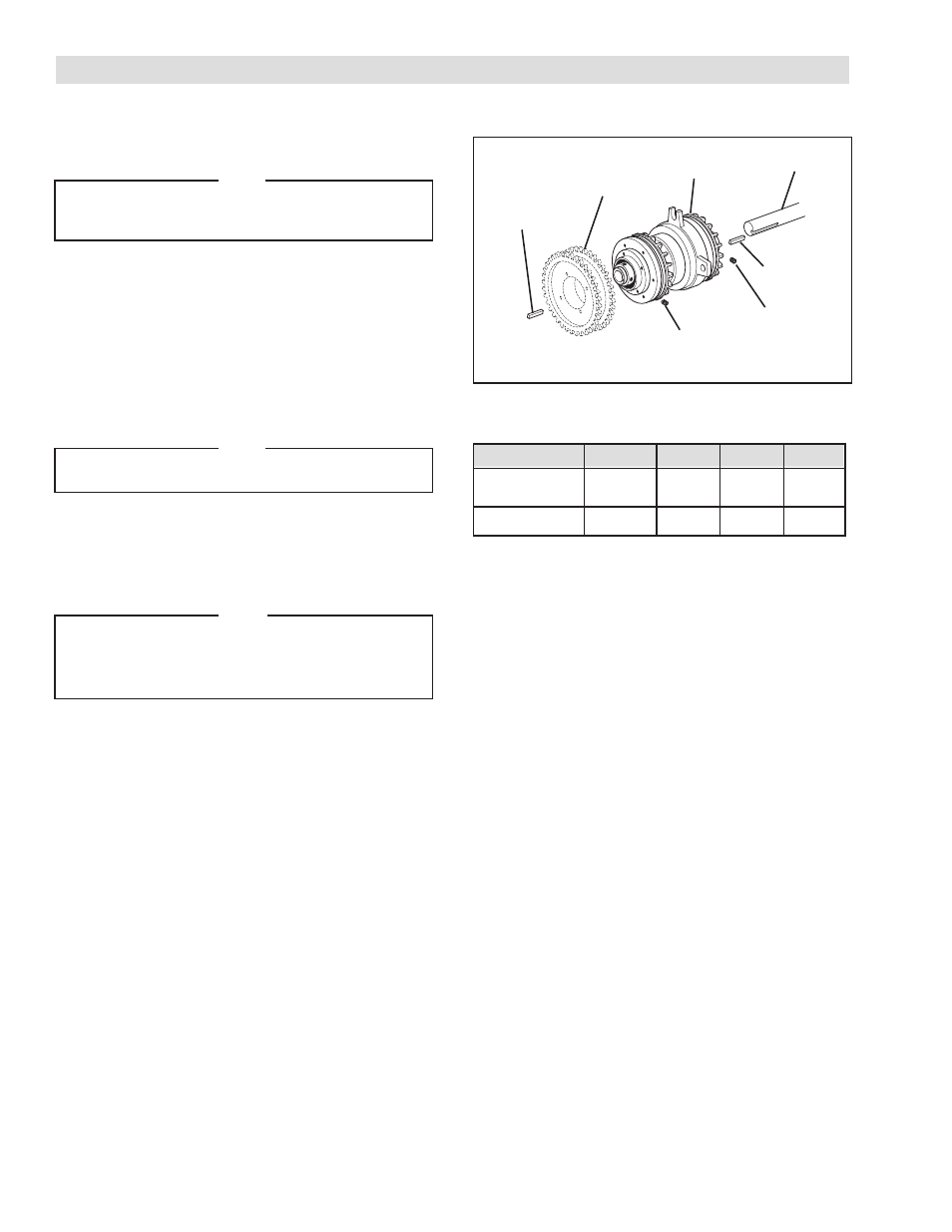
Refer to Figure 1.
NOTE
These are "hub-stop" clutch-brakes. They stop the shaft on
which they are mounted. Therefore, they must be mounted on
the driven shaft.
1. Secure a customer supplied sheave or sprocket to the Clutch-
Brake.
2. Insert the first Key (Item 30) into the shaft.
3. Slide the Clutch-Brake onto shaft and key; then, insert the
second Key (Item 30).
4. Tighten Set Screws (Items 27 and 28) to the recommended
torque (See Table 1).
NOTE
If a bushing for smaller diameter shafts is required, use a
bushing on both ends of the Clutch-Brake.
5. Align air inlet ports to a six o’clock down position to allow
condensation to drain out of exhaust port.
6. Fasten one of the ears of the Clutch-Brake to a fixed member
of the machine.
NOTE
The Piston Air Chamber (Item 7) floats axially approximately
1/16 inch [1.59 mm] during operation. Make sure securing
pin allows 1/16 inch to 1/8 inch [1.59 mm to 3.18 mm]
movement of Piston Air Chamber.
TABLE 1
RECOMMENDED TIGHTENING TORQUES
FIGURE 1
Shaft
Key
(Item 30)
Set Screw
(Item 28)
Set Screw
(Item 27)
Key
(Item 30)
Clutch-Brake
Sheave
or
Sprocket
DESCRIPTION
FWCB
LWCB
MWCB
HWCB
35 In. Lbs.
80 In. Lbs. 80 In. Lbs. 23 Ft. Lbs.
Set Screw (Item 27)
[3.9 N•m]
[8.9 N•m]
[8.9 N•m] [31.2 N•m]
20 In. Lbs.
20 In. Lbs. 80 In. Lbs.
— —
Set Screw (Item 28)
[2.2 N•m]
[2.2 N•m]
[8.9 N•m]
— —
.
- HWCB 832501 HWCB 832913 HWCB 832401 HWCB 832600 HWCB 832400 HWCB 832500 HWCB 832700 HWCB 832800 HWCB 832900 HWCB 832941 HWCB 832902 LWCB 828901 HWCB 832907 FWCB 827111 FWCB 826700 FWCB 826800 FWCB 826900 FWCB 827000 FWCB 827100 LWCB 828300 LWCB 828400 LWCB 828500 LWCB 828600 LWCB 828700 LWCB 828800 LWCB 828900 LWCB 828942 LWCB 828904 MWCB 830603 MWCB 830801 MWCB 830601 FWCB 827101 LWCB 828301 LWCB 828907 MWCB 830602 MWCB 830301 MWCB 830811 MWCB 830600 MWCB 830700 MWCB 830300 MWCB 830400 MWCB 830500 MWCB 830800 MWCB 830841 MWCB 830803 MWCB 830802 FWCB 847801 MWCB 848001 LWCB 847901 LWCB 847907 MWCB 848002 HWCB 848102 HWCB 848100 FWCB 847800 LWCB 847900 MWCB 848000