Nexen FM 625 BISSC 827251 User Manual
Page 11
11
FORM NO. L-20250-E-0114
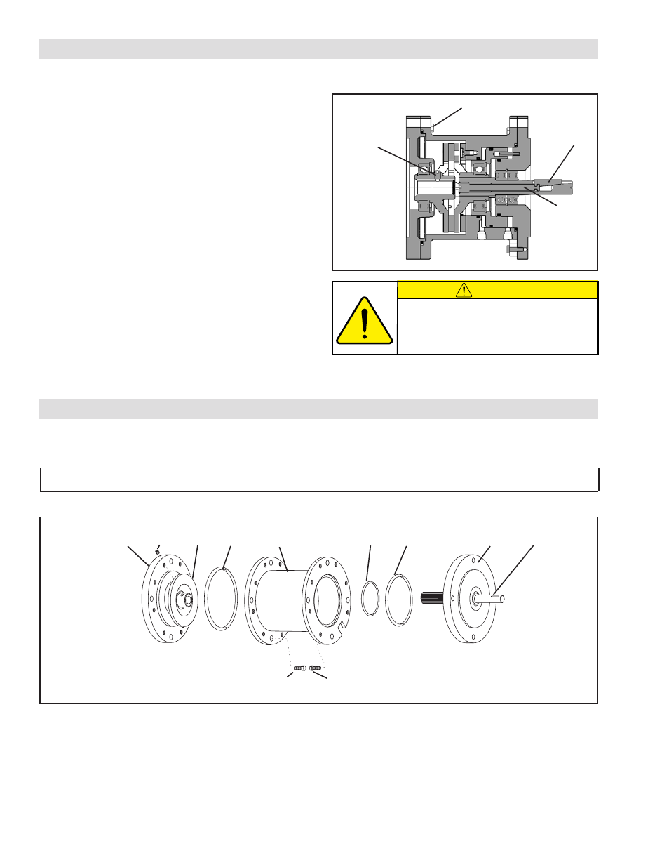
Refer to Figure 11.
1. Remove the eight Hex. Head Cap Screws (Item 27), Female
Pilot (Item 34), Drive Disc (Item 4), and O-Ring Seal (Item
33) from the FMCBE Assembly.
2. Remove the seven Hex. Head Cap Screws (Item 13), Male
Pilot (Item 20), Bearings (Item 19), Stub Shaft (Item 23), and
O-Ring Seals (Items 21 and 22).
Refer to the parts list for details.
1. Model 625: Remove Hex Head Cap Screws (Item 27,
29) that secure the housing (Item 1) FMCBE to the
motor or input unit; then loosen Set Screw (Item 26)
and slide the motor or input unit off the FMCBE.
Model 875: Remove Hex Head Cap Screws (Item
27) that secure the FMCBE Housing (Item 1) to the
Female Pilot (Item 34); then loosen Set Screw (Item
31), remove the Hex Head Cap Screws (Item 29) and
remove the Female Pilot from the motor or input unit.
2. Slowly unscrew the Bar (Item 38) one-half turn to
release the Key (Item 25).
3. Remove the FMCBE from the gear reducer.
FMCBE WITH LOCKING KEY REMOVAL
CAUTION
Unscrewing the Bar (Item 38) more
than one-half turn will damage the bar.
PARTS REPLACEMENT
FIGURE 11
22
23
20
21
1
33
4
26
34
13
27
COMPONENT DISASSEMBLY
NOTE
If an Input Unit has been installed, it must be removed prior to servicing the FMCBE.
FMCBE
Key
(Item 25)
Cap Screw
(Item 27)
FIGURE 10
Bar
(Item 38)
Set Screw
(Item 26 or 31)