Nexen FM 625 BISSC 827251 User Manual
Page 5
5
FORM NO. L-20250-E-0114
NOTE
Align the air inlet ports to a down position to allow
condensation to drain out of the ports.
1. Insert customer supplied key into the motor shaft
keyway.
2. Slide the Female Pilot (Item 34) and the Drive Disc
(Item 4) onto the motor shaft.
3. Tighten the Set Screw (Item 26) to lock the Drive Disc
(Item 4) onto the motor shaft.
4. Coat the O-Ring Seal (Item 33) and the seal contact
surface with a film of O-Ring lubricant, then wipe off
any excess lubricant.
5. Place the O-Ring Seal (Item 33) onto the Female Pilot
O-Ring diameter (Item 34).
6. Slide the FMCBE Assembly onto the Female Pilot (Item
34) and the Drive Disc (Item 4).
NOTE
Use Loctite
®
242 on all fasteners.
7. Using four Nexen supplied 0.375-16 x 1.500" Hex.
Head Cap Screws (Item 29), secure the Female Pilot,
Drive Disc, and Housing (Item 1) to the motor.
34
4
26
33
27
29
FMCBE
Assembly
25
FIGURE 2
8. Tighten the Hex. Head Cap Screws (Item 29) to 15 Ft.
Lbs. [20.3 Nm] torque.
9. Using eight Nexen supplied 10-24 x 0.750" Hex. Head
Cap Screws (Item 27), secure the FMCBE to the
Female Pilot and Drive Disc.
10. Alternately and evenly tighten the eight Hex. Head Cap
Screws (Item 27) to 21 In. Lbs. [2.4 Nm] torque.
BISSC CERTIFIED FMCBE MOUNTED ON A C-FACED MOTOR
INSTALLATION
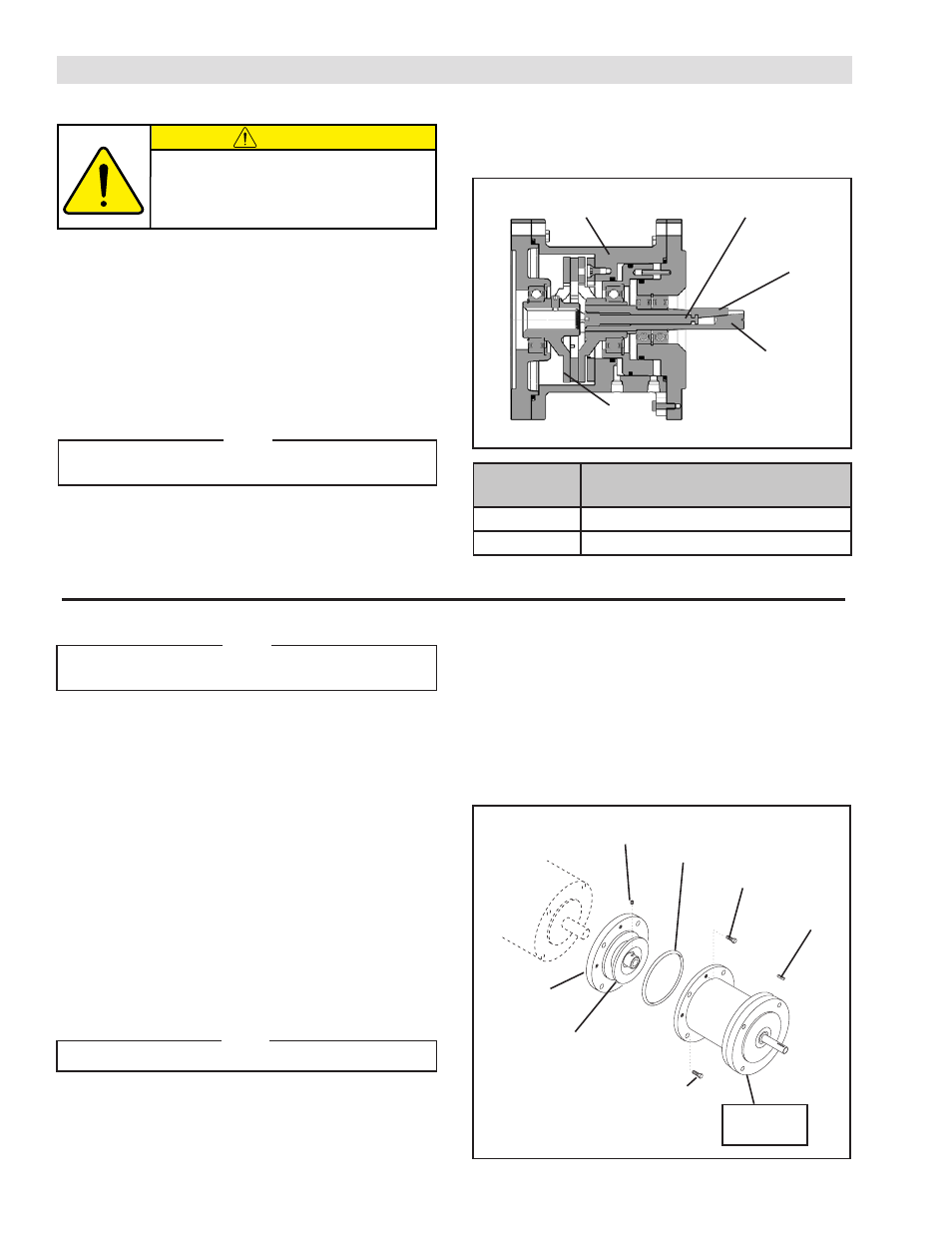
BISSC CERTIFIED FMCBE WITH LOCKING KEY
Refer to Figures 1 & 2.
1. Coat the threads of the Bar (Item 38) with Loctite
®
242;
then, thread the Bar into the Stub Shaft (Item 23) until
the end of the Bar is visible in the keyway slot of the
Stub Shaft.
2. Apply a thin film of Never-Seez
®
to Key (Item 25).
3. Place the Key (Item 25) into the keyway of the Stub
Shaft (Item 23).
NOTE
Align the air inlet port to a down position to allow
condensation to drain out of the air chamber.
4. Slide the FMCBE output shaft into the gear reducer.
5. Secure the FMCBE to the gear reducer, using customer
supplied socket head cap screws, lock washers, and
nuts.
CAUTION
This unit is not intended for foot
mounting. Flange mount the FMCBE
with Locking Key only.
TABLE 1
Bar
(Item 38)
Key
(Item 25)
Stub Shaft
(Item 23)
FIGURE 1
Housing
(Item 1)
Drive Disc
(Item 4)
6. Tighten the Bar (Item 38) to the recommended
tightening torque (See Table 1).
Model
Recommended Tightening Torque
Item 38
FMCBE-625
6.8 Nm (5 ft-lb)
FMCBE-875
6.8 Nm (5 ft-lb)