Nexen FM 625 BISSC 827251 User Manual
Page 6
6
FORM NO. L-20250-E-0114
Align the air inlet ports to a down position to allow
condensation to drain out of the ports.
Refer to Figure 3.
1. Insert customer supplied key into the motor shaft keyway.
2. Slide the Female Pilot (Item 34) and the Drive Disc (Item 4)
onto the motor shaft.
3. Tighten the Set Screw (Item 26) to lock the Drive Disc (Item
4) onto the motor shaft.
4. Coat the O-Ring Seal (Item 33) and the seal contact surface
with a film of O-Ring lubricant, then wipe off any excess
lubricant.
5. Place the O-Ring Seal (Item 33) onto the Female Pilot (Item
34) O-Ring diameter.
6. Slide the FMCBE Assembly onto the Female Pilot (Item 34)
and the Drive Disc (Item 4).
NOTE
Use Loctite
®
242 on all fasteners.
7. Using eight Nexen supplied 10-24 x 0.750" Hex. Head Cap
Screws (Item 27), secure the FMCBE Assembly to the Fe-
male Pilot (Item 34) and Drive Disc (Item 4).
8. Alternately and evenly tighten the eight Hex. Head Cap
Screws (Item 27) to 21 In. Lbs. [2.4 Nm] torque.
OPTIONAL INPUT UNIT
Refer to Figure 4.
1. Coat the O-Ring Seal (Item 59) and the seal contact surface
with a film of O-Ring lubricant; then, wipe off any excess
lubricant.
2. Place the O-Ring Seal (Item 59) into the seal groove of the
Input Unit Bearing Flange (Item 20).
3. Slide the Female Pilot (Item 34) and Drive Disc (Item 4) onto
the Input Unit shaft.
4. Tighten the Set Screw (Item 26) to lock the Drive Disc (Item
4) onto the motor shaft.
5. Coat the O-Ring Seal (Item 33) and the seal contact surface
with a film of O-Ring lubricant; then, wipe off any excess
lubricant.
6. Place the O-Ring Seal (Item 33) onto the seal diameter of
the Female Pilot (Item 34).
7. Slide the FMCBE Assembly onto the Female Pilot (Item 34)
and the Drive Disc (Item 4).
NOTE
Use Loctite
®
242 on all fasteners.
8. Using four Nexen supplied 0.375-16 x 1.750" Hex. Head
Cap Screws (Item 62) and Acorn Nuts (Item 63), secure the
Female Pilot, Drive Disc, and FMCBE Assembly to the Input
Unit (Item 20).
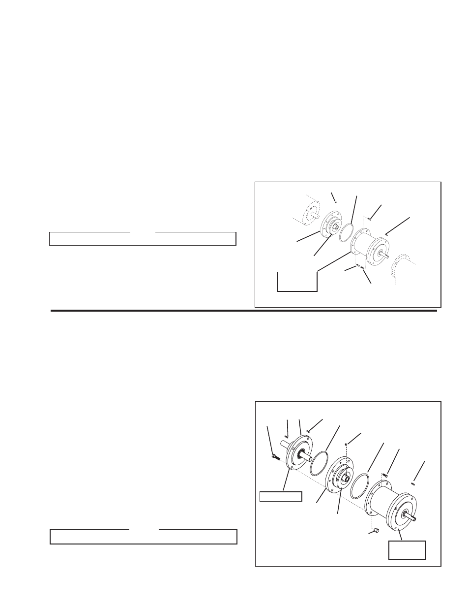
FIGURE 4
59
Input Unit
34
4
26
33
62
63
25
20
27
19
19
FMCBE
Assembly
9. Alternately and evenly tighten the four Hex. Head Cap Screws
(Item 62) to 15 Ft. Lbs. [20.3 Nm] torque.
10. Using eight Nexen supplied 10-24 x 0.750" Hex. Head
Caps Screws (Item 27), secure the FMCBE Assembly to
the Female Pilot and Drive Disc.
11. Alternately and evenly tighten the eight Hex. Head Cap
Screws (Item 27) to 21 In. Lbs. [2.4 Nm] torque.
9. Using four Nexen supplied 0.375-16 x 1.500" Hex. Head
Cap Screws (Item 29), secure the Female Pilot, Drive Disc,
and FMCBE Assembly to the motor.
10. Alternately and evenly tighten the four Hex. Head Cap Screws
(Item 29) to 15 Ft. Lbs. [20.3 Nm] torque.
11. Slide the FMCBE Assembly input shaft and motor into the
gear reducer.
12. Using four supplied 0.375-16 x 1.250" Hex. Head Cap
Screws (Item 36), secure the Male Pilot end of the FMCBE
Assembly to the gear reducer.
13. Alternately and evenly tighten the four Hex. Head Cap Screws
(Item 36) to 15 Ft. Lbs. [20.3 Nm] torque.
BISSC CERTIFIED FMCBE MOUNTED BETWEEN A C-FACED MOTOR AND GEAR REDUCER
FIGURE 3
34
4
26
33
27
29
36
25
FMCBE
Assembly