Caution – Nexen FM 625 BISSC 827251 User Manual
Page 14
14
FORM NO. L-20250-E-0114
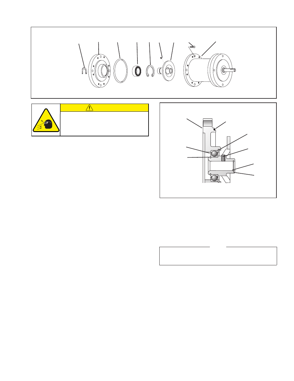
FEMALE PILOT BEARING (Item 2) AND O-RING SEAL (Item 33)
Refer to Figures 16 & 17.
1. Remove the Retaining Ring (Item 6) from the Drive Disc (Item
4).
2. Fully supporting the Female Pilot (Item 34), press out the
Drive Disc (Item 4).
3. Remove the Retaining Ring (Item 3) from the Female Pilot
(Item 34).
4. Press the Bearing (Item 2) out of the Female Pilot (Item 34).
5. Fully supporting the Female Pilot (Item 34) and pressing on
the outer bearing race, press the new Bearing (Item 2) into
the Female Pilot.
6. Install the Retaining Ring (Item 3) into the Female Pilot (Item
34).
7. Fully supporting the inner race of Bearing (Item 2), press the
Drive Disc (Item 4) into the Bearing and Female Pilot.
8. Install the Retaining Ring (Item 6) onto the Drive Disc (Item
4) (See Figures 16 and 17).
9. Clean the O-Ring contact surfaces of the Female Pilot (Item
34) and Housing (Item 1) with fresh safety solvent.
FIGURE 16
6
33
2
3
34
26
4
27
1
FIGURE 17
34
3
2
6
26
5
4
33
CAUTION
Working with spring loaded or tension
loaded fasteners and devices can cause
injury. Wear safety glasses and take the
appropriate safety precautions.
10. Coat the O-Ring contact surfaces of the Female Pilot and
Housing with fresh O-Ring lubricant and wipe off any excess
lubricant.
11. Coat the new O-Ring Seal (Item 33) with fresh O-Ring
lubricant and place the new O-Ring onto the Female Pilot.
NOTE
Do not tighten the Hex. Head Cap Screws (Item 27)
until the Clutch Brake has been installed on the unit it
is controlling.
12. Secure the Female Pilot (Item 34) to the Housing with the
eight Hex. Head Cap Screws (Item 27).