Input unit, Caution – Nexen FM 625 BISSC 827251 User Manual
Page 15
15
FORM NO. L-20250-E-0114
INPUT UNIT
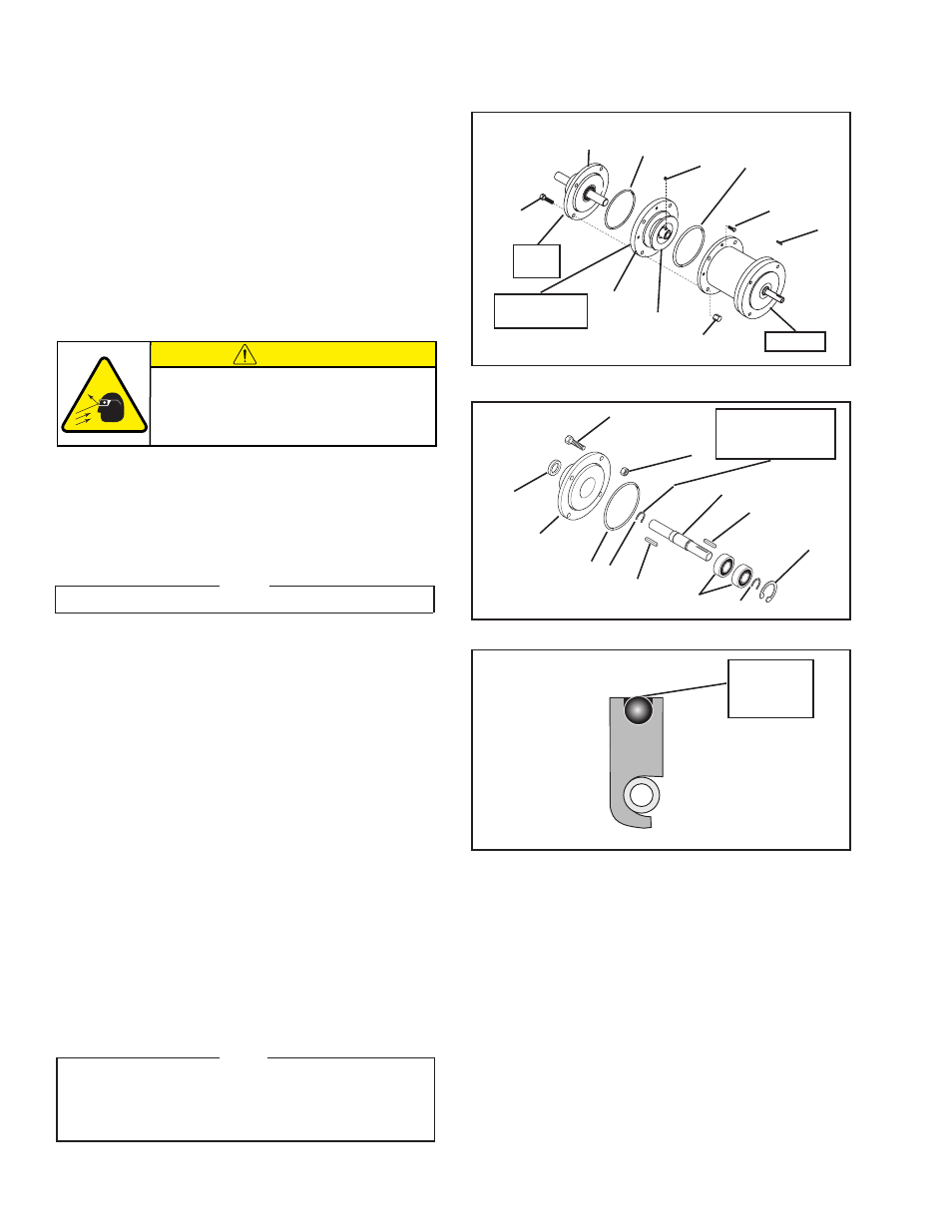
Refer to Figures 18 - 20.
1. Remove the eight Hex. Head Cap Screws (Item 27).
2. Remove the four Hex. Head Cap Screws (Item 62) and Acorn
Nuts (Item 63).
3. Remove the Female Pilot Assembly, O-Ring Seal (Item 33),
and the Input Unit from the FMCBE.
4. Remove the Set Screw (Item 26) and slide the Female Pilot
(Item 34) off the Input Unit (Item 20).
5. Remove the O-Ring Seal (Item 59).
6. Remove both Keys (Item 19).
7. Remove the Retaining Ring (Item 58).
8. Supporting the Bearing Flange (Item 20), press the Stub
Shaft (Item 11) and Bearings (Item 30) out of the Bearing
Flange.
9. Remove one Retaining Ring (Item 35).
NOTE
One Retaining Ring must remain on the Stub Shaft.
10. Press the Stub Shaft (Item 11) out of the Bearings (Item 30).
11. Press the new Bearings (Item 30) onto the Stub Shaft (Item
11) until they are seated against the Retaining Ring (Item
35) on the Stub Shaft.
12. Install the Retaining Ring (Item 35) that was removed from
the Stub Shaft.
13. Remove the Variseal
TM
(Item 13) from the Bearing Flange
(Item 20).
14. Supporting the Bearing Flange (Item 20) and pressing on
the outer races of Bearings (Item 30), press the Stub Shaft
and Bearings into the Bearing Flange until they are seated
against the step in the Bearing Flange.
15. Install the Retaining Ring (Item 58).
16. Coat the outer seal of the Variseal
TM
with a thin film of O-Ring
lubricant.
17. Press the Variseal
TM
with the spring facing out onto the Stub
Shaft and into the Bearing Flange.
18. Apply a drop of Loctite
â
242 to the Keys (Item 19).
19. Press the Keys (Item 19) into the Stub Shaft (Item 11).
NOTE
After assembly is complete, the Stub Shaft should be
rotated and checked for smooth operation. If drag is
apparent, move the Stub Shaft in and out to release
pressure on the bearing cage and recheck for smooth
operation.
FIGURE 19
62
13
20
63
59
11
19
30
58
35
19
35
Do not remove
this Retaining
Ring.
FIGURE 18
62
Input
Unit
59
34
4
26
33
27
25
63
FMCBE
20
Female Pilot
Assembly
Apply
O-Ring
lubricant.
FIGURE 20
CAUTION
Working with spring loaded or tension
loaded fasteners and devices can cause
injury. Wear safety glasses and take the
appropriate safety precautions.