Caution – Nexen FM 625 BISSC 827251 User Manual
Page 13
13
FORM NO. L-20250-E-0114
Refer to Figures 14 & 15.
1. Remove the Key (Item 25).
2. Remove the Retaining Ring (Item 24).
3. Press the Stub Shaft (Item 23) out of the Male Pilot (Item 20)
and Bearings (Item 19).
NOTE
One Bearing (Item 19) will come out of the Male Pilot
(Item 20) on the Stub Shaft (Item 23).
4. Press the Bearing (Item 19) that is still in the Male Pilot (Item
20) out of the Male Pilot.
5. Using a bearing puller, remove the second Bearing (Item 19)
from the Stub Shaft (Item 23).
6. Supporting the Male Pilot and pressing on the outer bearing
race, press one new Bearing (Item 19) into the Male Pilot
until it is seated against the Retaining Ring (Item 18) inside
the Male Pilot.
7. Support the inner race of the bearing pressed into the Male
Pilot in Step 6 and press the Stub Shaft (Item 23) into the
Bearing (Item 19) and Male Pilot (Item 20).
8. Pressing on both the inner and outer races, press the second
Bearing (Item 19) onto the Stub Shaft (Item 23) and into the
Male Pilot (Item 20).
9. Install the Retaining Ring (Item 24).
10. Remove the O-Rings Seals (Items 21 and 22).
11. Clean the O-Ring Seal contact surfaces of the Housing (Item
1) and Male Pilot (Item 20) with fresh safety solvent.
12. Coat the O-Ring contact surfaces of the Male Pilot (Item 20)
and Housing (Item 1) with fresh O-Ring lubricant and wipe
off the excess lubricant.
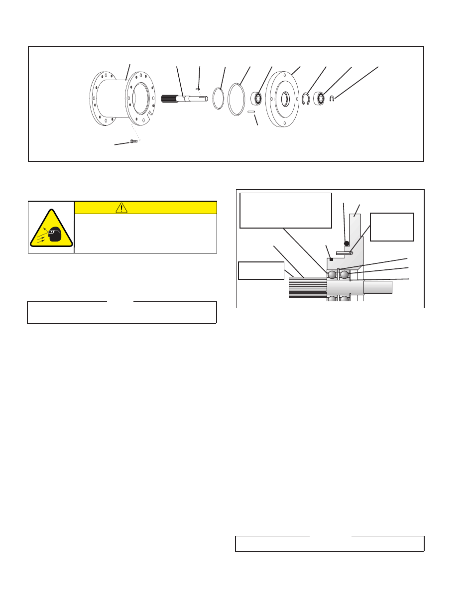
MALE PILOT BEARINGS (Item 19) AND O-RING SEALS (Item 21 AND 22)
FIGURE 14
1
25
22
21
19
20
18
19
24
17
13
23
13. Coat the new O-Ring Seals (Item 21 and 22) with fresh
O-Ring lubricant.
14. Install the new O-Ring Seals (Item 21 and 22) onto the Male
Pilot (Item 20).
15. Coat the splined end of the Stub Shaft (Item 23) with a thin
film of Never-Seez
®
.
16. Align the Slotted Spring Pin (Item 17) in the Male Pilot with the
hole in the Piston and carefully slide the Male Pilot Assembly
into the Housing and Piston/Splined Disc Assembly.
17. Apply a drop of Loctite
®
242 to the threads of the seven Hex.
Head Cap Screws (Item 13).
18. Using the seven Hex. Head Cap Screws (Item 13), secure
the Male Pilot to the Housing.
19. Alternately and evenly tighten the seven Hex. Head Cap
Screws (Item 13) to 21 In. Lbs. [2.4 Nm].
20. Non-locking key units only: apply a drop of Loctite
®
242
to the Key (Item 25).
WARNING
Do not use Loctite
®
on Locking Key Units
21. Press the Key (Item 25) into the Stub Shaft (Item 23).
This Bearing (Item 19)
will come out with the
Stub Shaft and is the first
to be pressed in place.
FIGURE 15
23
22
19
24
18
20
Slotted
Spring Pin
(Item 17)
Apply
Never-Seez
®
21
CAUTION
Working with spring loaded or tension
loaded fasteners and devices can cause
injury. Wear safety glasses and take the
appropriate safety precautions.