Multiple clock networks, Multi-cycle clock – Altera HardCopy II Clock Uncertainty Calculator User Manual
Page 30
3–4
Altera
Corporation
HardCopy II Clock Uncertainty Calculator User Guide
Various Clock Structures
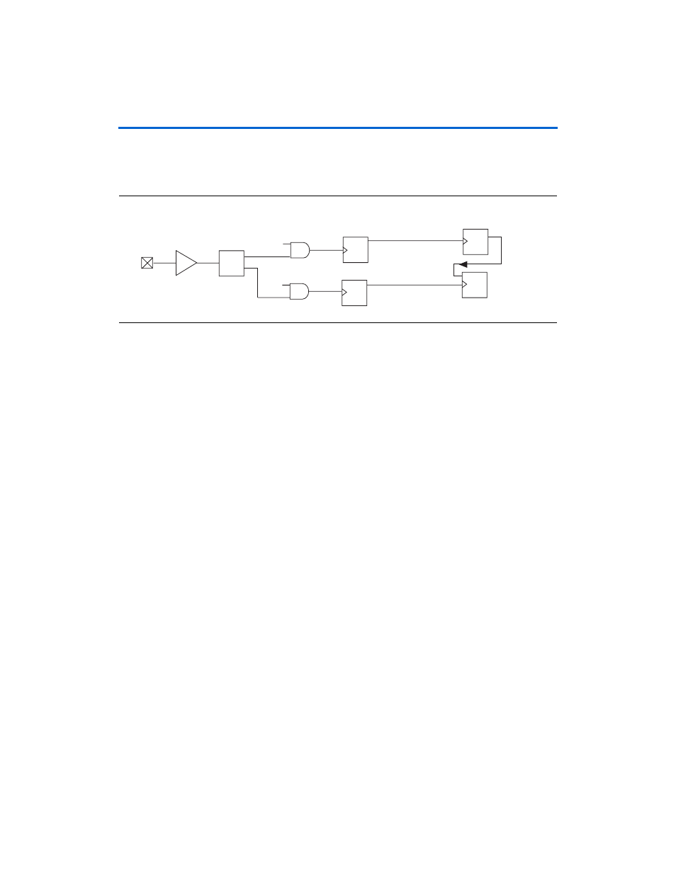
Multiple Clock Networks
shows an example of multiple clock networks.
Figure 3–6. Multiple Clock Networks
The
CLK1 and CLK4 networks are accounted for by the clock uncertainty
calculator, but the
CLK2, CLK3, CLK5, and CLK6 networks are ignored.
Therefore, you should add 25 ps for each ignored clock network to the
setup and hold clock uncertainty for the example in
.
Multi-Cycle Clock
The multi-cycle clock occurs when there is a delay (
Δt) that is greater than
the clock period between the source register and destination register.
Refer to
. The default hold clock uncertainty value is
considered that the source clock and destination clock are on the same
edge.
When the multi-cycle path timing exception is set, you need pay attention
for the hold clock uncertainty of Intra-clock transfers since the possible
hold checks are not at the launch edge for both source and destination
clock due to the extra delay (
Δt) on the data path.
PLL
INBUF
Source
Clock
Destination
Clock
Source
Register
Destination
Register
CLK1
CLK2
CLK4
CLK3
CLK6
CLK5