Act single channel wireless receiver – MIPRO act707s-ii(2ce149)b User Manual
Page 4
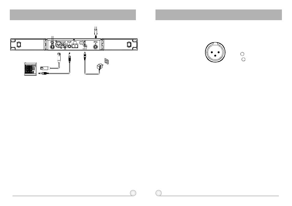
3: COLD -
+
1: GND
2: HOT
3
2
1
4
5
ACT SINGLE CHANNEL WIRELESS RECEIVER
ACT SINGLE CHANNEL WIRELESS RECEIVER
(Fig.3)
3. INSTALLATION OF THE RECEIVER
1.
Install 2 separate antennas on the antenna sockets (5), (11) on the rear
panel. Illustrated in
2.
Connecting the power supply:
3.
Audio Output Connection:
Fig. 3.
Connect the AC/DC adapter cable to DC
12V INPUT JACK (10), then plug the adapter unit into an appropriate AC
outlet with caution to the correct voltage under both AC outlet and
adapter marked. Illustrated in Fig. 3.
(a) Unbalanced Level Switch (7) Setting Position: When inputs the unbalanced
output of a receiver into "AUX-IN" input jack of a mixer or amplifier or "Electric
Guitar", switch the Level Switch (7) to the right "LINE" position. Low
sensitivity may occur if switch to the wrong position. When input the
unbalanced output of a receiver into the "MIC-IN" input jack of a mixer or
amplifier; switch the Level Switch (7) to the left "MIC" position. Over load
distortion may occur if switch to the wrong position. When using electric guitar,
don't use "MIC" position as it may have generated insufficient level.
(b) Unbalanced Output: Using audio output cable attached with "PHONE PLUG"
type, connect one end from the unbalanced output jack (8) of the receiver,
and theother end to the "LINE-IN" input jack of the amplifier, as shown in Fig.
3.
(c) Balanced Output: Using audio output cables attached with "XLR" or
"Cannon" type, connect one end from the balanced output jacks (6) of the
receiver, and the other end to the "MIC IN" input jack of the mixer or
amplifier, as shown in Fig. 3. (The characteristic of the 3-pin connector is
as shown in Fig. 4
(Fig.4)
(d) Guitar Output: Using audio output cable attached with "PHONE PLUG" type,
plug one end from the unbalanced output jack of a receiver, and the other
end to the input jack of a guitar amplifier. Switch the Level Switch (7) to
"LINE" position.
4.
Antenna Socket: The antenna socket provides 8 Volt DC power, which
enable you to pair with MIPRO's antenna booster directly. When the
connecting cable for the antenna is more than 10 meter, it is
recommended to install antenna booster to make up the signal loss
caused by the cable and to ensure the sensitivity of reception.
4. RECEIVER OPERATING PROCEDURES
1.
Turn volume controls of the mixer in use to a minimum setting before turn
on the microphones or transmitters. After switches on the receiver, the
power switch red indicator illuminates to denote normal power status.
2.
Under normal circumstances, the RF indicator lights up when a
microphone or transmitter is turned on near the receiver to indicate the
receiver is ready for normal operation. Once sounds to the microphone
and the AF indicators will glow according to the strength of sound level.
If no LED glows or no sound outputs, the system is not function properly,
thus it must be checked
3.
The microphone output level needs to be adjusted at the amplifier or
mixer. No need to adjust at the receiver itself.