Applied Motion 1240i User Manual
Page 11
-22-
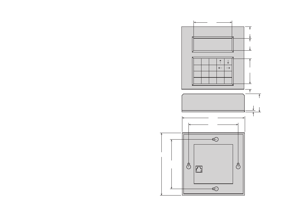
Mechanical Outline - Optional MMI
4.90
4.90
1.38
0.13
3.875
CENTERED
3.875
CENTERED
1 2 3
4 5 6
7 8 9
YES
NO
.
0
SPACE BKSP ENTER
2.988
1.975
0.425
0.963
0.960
-21-
Amplifiers
Power Supply
Inputs
Outputs
Microstepping
Motion Update
Physical
Connectors
Agency
Approvals
Dual H-bridge, 3 state, pulse width modulated (PWM) switching at 25
kHz. 0.1 - 1.2 amps/phase output current, software selectable. 48 watts
maximum output power. Automatic idle current reduction (software
programmable) reduces current to motor when idle. Minimum motor
inductance is 0.8 mH.
Accepts 12 - 42 VDC power supply. 1.2 amps or greater at 24VDC.
5 - 24 VDC, optically isolated. 2200 ohms internal resistance. Can be
configured for sinking (NPN) or sourcing (PNP) signals.
Analog Input - not currently supported by Si Programmer, may be read
in SCL mode using “RA or “IA” commands.
Optically isolated. 5-24 VDC, 100 mA max.
13 software selectable resolutions. Steps per revolution with 1.8° mo-
tor: 2000, 5000, 10000, 12800, 18000, 20000, 21600, 25000, 25400,
25600, 36000, 50000, 50800. Waveform: pure sine.
12800 Hz.
Constructed on 0.063 inch thick printed circuit board. Four mounting
holes, 0.156 inch diameter. Overall size : 3.00 x 4.00 x 0.65 inches.
0.15 lb. 0 to 50°C ambient operating temperature. See page 20 for
detailed drawing.
European style screw terminal blocks. Power Supply and Motor: 6
position. Wire size: AWG 16 - 28. Signal input/output: 19 position.
Wire size: AWG 16 - 28.
CE compliant to EN55011A, EN50082-1(1997)
Technical Specifications