Applied Motion 1240i User Manual
Page 3
-5-
Getting Started
To use your 1240i motor control, you will need the following :
• a power supply (see page7 for help choosing one).
• a compatible step motor (see page 19 for recommended motors).
• a small flat blade screwdriver for tightening the connectors - an Applied Motion
Products screwdriver suitable for this purpose is included with your drive.
• a personal computer running Windows 3.1, 95, 98, NT, W2K, XP, Vista or Vista64
or Windows7 with a 9 pin serial port (486 or better with 8 MB ram recommended)
• the Si Programmer
TM
software that came with your 1240i
• the programming cable that came with your 1240i
• Si Programmer
TM
software manual - on the CD that came with your 1240i
The sketch below shows where to find the important connection and adjustment
points. Please examine it now.
There are two versions of the 1240i, one has an added 3-pin connector CN7.
All Mating connectors included.
-6-
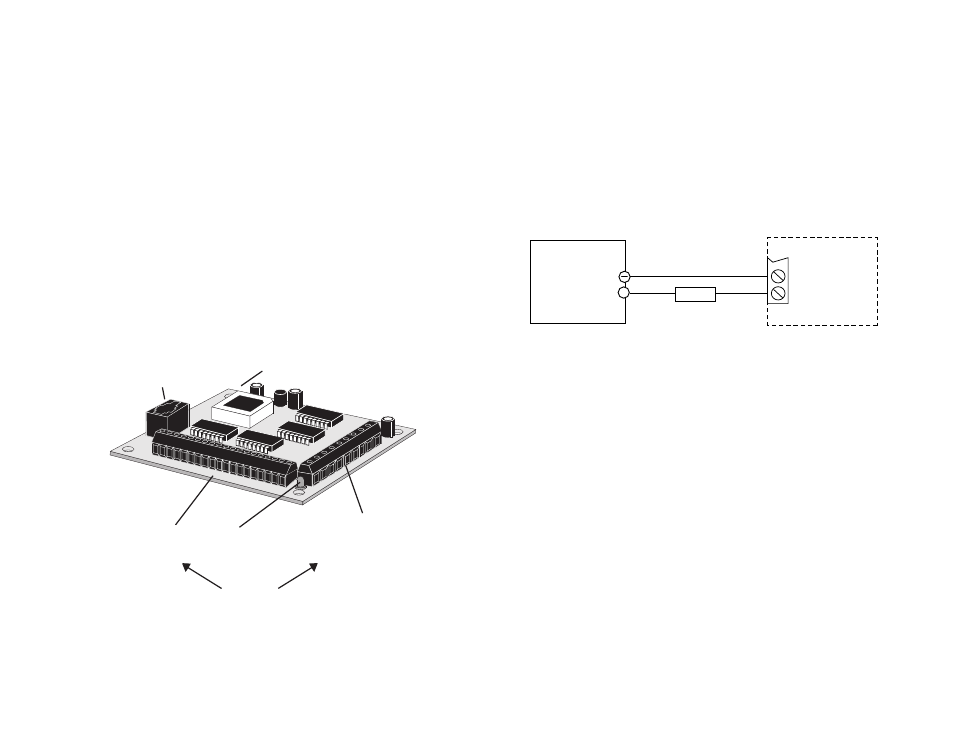
Connecting the Power Supply
If you need information about choosing a power supply, please read Choosing a
Power Supply on the next page.
If your power supply does not have a fuse on the output or some kind of short circuit
current limiting feature, you need to put a 1 amp fast acting fuse between the drive
and the power supply. Install the fuse on the + power supply lead.
Connect the motor power supply as shown below. Use no smaller than 18 gauge
wire. Be careful not to reverse the wires. Reverse connection may destroy your
driver, void your warranty and generally wreck your day.
1240i
1A fuse
-
V +
DC Power
Supply
12 - 42 V
+
i/o connector
inputs 1,2,3,4
jog cw
jog ccw
cw limit
ccw limit
out 1,2,3
power/motor
connector
DC power supply
motor
power LED
mounting hole (1 of 4)
pc/mmi
connector
* Always use the blue & white
Applied Motion screwdriver
with these connectors.
Larger screwdrivers may remove
the plastic dimples that prevent
the screws from falling out.
Power LED Diagnostics
The power LED is also used as a status indicator for alarm codes for the drive.
Alarm codes are shown below:
Code:
Message:
2 red, 1 green
ccw limit
2 red, 2 green
cw limit
1 red, 3 green
subroutine stack overflow
2 red, 3 green
subroutine stack underflow
4 red, 3 green
bad instruction in Si program (memory or software error)
7 red, 1 green
serial communication error
solid red
firmware re-flash mode. Si Firmware Downloader can be
used to recover drive, contact technical support.