Applied Motion 1240i User Manual
Page 6
-11-
If the sensor output goes low at the limit, select the option “closed”. If the output is
open, or high voltage, choose “open”.
Other sensors have sourcing outputs. That means that current can flow out of the
sensor output, but not into it. In that case, wire the sensor this way:
If the sensor output goes high at the limit, choose the program option “closed”. if
the output is low at the limit, select “open”.
Wiring a Mechanical Limit Switch
You can use normally open or normally closed limit switches. Either way, wire them
as shown here.
Wiring a Limit Sensor
Some systems use active limit sensors that produce a voltage output rather than a
switch or relay closure. These devices must be wired differently than switches.
If your sensor has an open collector output or a sinking output, wire it like this:
1240i
CCW LIMIT+
CCW LIMIT-
CW LIMIT-
+
5-24
VDC
SUPPLY
-
CW LIMIT+
1240i
CW LIMIT-
+
DC
Power
Supply
–
Limit
Sensor
CW LIMIT+
Wiring for Sinking or Open Collector Output
output
+
–
1240i
LIMIT-
+
DC
Power
Supply
–
Proximity
Sensor
LIMIT+
Wiring for Sourcing Output
output
+
–
-12-
Wiring Inputs
The 1240i input circuits can be used with
sourcing or sinking signals, 5 to 24 volts.
This allows connection to many TTL circuits,
PLCs, relays and mechanical switches.
Because the input circuits are isolated, they
require a source of power. If you are con-
necting to an open collector TTL circuit or
to a PLC, you should be able to get power
from the PLC or TTL power supply. If you
are using relays or mechanical switches,
you will need a 5-24 V power supply. This
also applies if you are connecting the 1240i
inputs to another Si product from Applied
Motion, like the Si-100 indexers or the
3540i, Si3540, Si5580, 7080i and Si4500
indexer-drives.
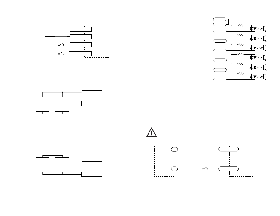
Connecting an Input to a Switch or Relay
Use normally open momentary switch to trigger 1240i using Wait Input instruction.
Use single throw switch for parameter selection using If Input instruction.
Use normally open momentary switch for jogging.
Note: If current is flowing into or out of an 1240i input, the logic state of that input is
low. If no current is flowing, or the input is not connected, the logic state is high.
The diagrams on the following pages show how to connect 1240i inputs to various
devices.
The maximum voltage that can be applied to an input terminal
is 24 volts DC. Never apply AC voltage to an input terminal.
2200
2200
2200
2200
2200
2200
inside 1240i
COM
COM
IN1
IN2
IN3
IN4
JOG CW
JOG CCW
1240i
switch or relay
(closed=logic low)
IN
COM
5-24
VDC
Power
Supply
-
+