Applied Motion 1240i User Manual
Page 5
-9-
Connecting to the PC
•Locate your computer within 6 feet of the 1240i. Connect the drive to your PC using
the programming cable supplied.
Never connect the 1240i to a telephone circuit. It uses the
same connectors and cords as telephones and modems, but the
voltages are not compatible.
Programming Note: Always apply power to the 1240i after the Si
TM
Programmer
software is running on your PC.
A+
A–
B+
B–
8
lead
motor
8 Leads Series Connected
8 Leads Parallel Connected
A+
A–
B+
B–
8
lead
motor
Orange
Org/Wht
Blk/Wht
Black
Red Red/
Wht
Yel/
Wht
Yellow
Orange
Org/
Wht
Blk/Wht
Black
Red
Red/Wht
Yel/
Wht
Yel
low
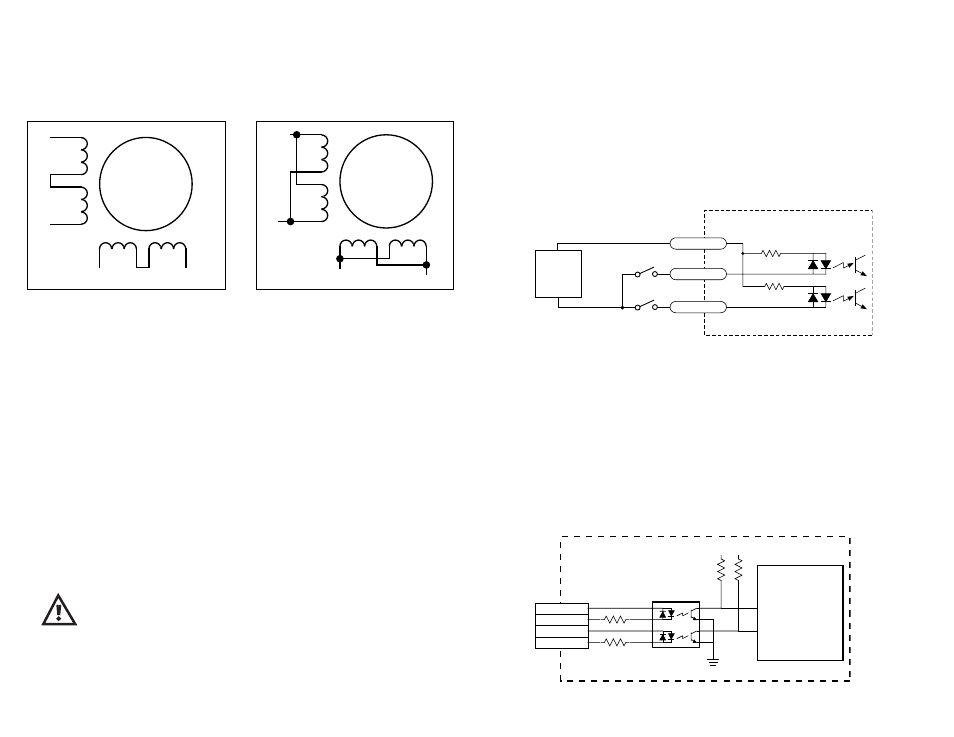
Eight lead motors can also be connected in two ways: series and parallel. As
with six lead motors, series operation gives you more torque at low speeds and less
torque at high speeds. In series operation, the motor should be operated at 30%
less than the rated current to prevent overheating. The wiring diagrams for eight lead
motors are shown below.
-10-
Limit Switches
The 1240i has two limit switch inputs, LIMIT CW and LIMIT CCW. By connecting
switches or sensors that are triggered by the motion of the motor or load, you can
force the 1240i to operate within certain limits. This is useful if a program error
could cause damage to your system by traveling too far.
The limit inputs are optically isolated. This allows you to choose a voltage for your
limit circuits of 5 to 24 volts DC. This also allows you to have long wires on limit
sensors that may be far from the 1240i with less risk of intoducing noise to the
1240i. The schematic diagram of the limit switch input circuit is shown below.
Jogging
Two of the 1240i input terminals are provided for jogging the motor. The inputs are
labeled “JOG CW” and “JOG CCW”. Activating one of the inputs commands the
drive to move the motor at a pre-designated speed until the contact is opened. A
relay or mechanical switch can be used to activate the jog inputs. 5-24 volt circuitry
can be used. The schematic diagram of the input circuit is shown below.
If you’re using a switch or relay, wire one end to the JOG input and the other to the
power supply negative (-) terminal. Then connect the COM input to the power sup-
ply positive (+) terminal.
2200
2200
inside 1240i
COM
JOG CW
JOG CCW
+
5-24
VDC
SUPPLY
-
1240i
Controller
Chip
2200
10K
+5V +5V
3
4
1
2
CW LIMIT+
CW LIMIT–
CCW LIMIT+
CCW LIMIT–
inside 1240i