Applied Motion 1240i User Manual
Page 8
-16-
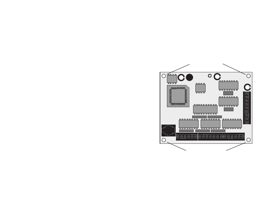
Mounting the Drive.
The 1240i has four 0.156 inch diameter holes in the circuit board for mounting.
Always use standoffs or spacers to support the 1240i: a 1240i with power connected
will be damaged if you set it on a conductive surface without supports. The standoffs
or spacers can be up to 0.25 inch in outer diameter. You can use #4 or #6 screws to
fasten the 1240i.
mounting holes
0.156 inch Diameter
0.156 inch Diameter
mounting holes
-15-
Microstepping
Most step motor drives offer a choice between full step and half step resolutions. In
full step mode, both motor phases are used all the time. Half stepping divides each
step into two smaller steps by alternating between both phases on and one phase on.
Microstepping drives like the 1240i precisely control the amount of current in each
phase at each step position as a means of electronically subdividing the steps even
further. The 1240i offers a choice of 13 step resolutions. The highest setting divides
each full step into 254 microsteps, providing 50,800 steps per revolution when us-
ing a 1.8
°
motor.
In addition to providing precise positioning and smooth motion, microstep drives
can be used for motion conversion between different units. The 25,400 step/rev
setting is provided as a means of converting motion from metric to english (there are
25.4 mm in an inch). Other settings provide step angles that are decimal degrees
(36,000 steps/rev makes the motor take 0.01
°
steps). Some settings are used with
lead screws. When the drive is set to 2000 steps/rev and used with a 0.2 pitch lead
screw, you get 0.0001 inches/step.
The microstep resolution of the 1240i is set by the Si Programmer
TM
software.