Applied Motion 1240i User Manual
Page 4
-7-
Choosing a Power Supply
Please follow the recommendations below for choosing a power supply:
Voltage
Chopper drives like the 1240i work by switching the voltage to the motor terminals
on and off while monitoring current to achieve a precise level of phase current. To
do this efficiently and silently, you’ll want to have a power supply with a voltage
rating at least five times that of the motor. Depending on how fast you want to run
the motor, you may need even more voltage than that. If you choose an unregulated
power supply, do not exceed 28 volts. This is because unregulated supplies are
rated at full load current. At lesser loads, like when the motor’s not moving, the
actual voltage can be up to 1.4 times the rated voltage. For smooth, quiet operation,
a lower voltage is better.
Current
The maximum supply current you could ever need is the sum of the two phase cur-
rents. However, you will generally need a lot less than that, depending on the motor
type, voltage, speed, and load conditions. That’s because the 1240i uses switching
amplifiers, converting a high voltage and low current into lower voltage and higher
current. The more the power supply voltage exceeds the motor voltage, the less cur-
rent you’ll need from the power supply. A motor running from a 24 volt supply can
be expected to draw only half the supply current that it would with a 12 volt supply.
We recommend the following selection procedure:
1) If you plan to use only a few drives, get a power supply with at least twice the
rated phase current of the motor.
2) If you are designing for mass production and must minimize cost, get one power
supply with more than twice the rated current of the motor. Install the motor in the
application and monitor the current coming out of the power supply and into the
drive at various motor loads. This will tell you how much current you really need so
you can design in a lower cost power supply. If you plan to use a regulated power
supply our PS50A24 is a good choice.
-8-
Connecting the Motor
Never connect or disconnect the motor to the driver when the
power is on.
Insulate unused motor leads separately, and then secure.
Never connect motor leads to ground or to a power supply.
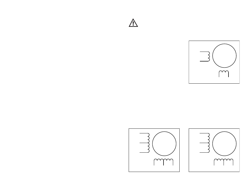
You must now decide how to connect your
motor to the drive.
Four lead motors can only be connected
one way. Please follow the sketch at the
right.
Six lead motors can be connected in series or center tap. In series mode, motors
produce more torque at low speeds, but cannot run as fast as in the center tap con-
figuration. In series operation, the motor should be operated at 30% less than the
rated current to prevent overheating. Wiring diagrams for both connection methods
are shown below.
Note: NC means not connected to anything.
A+
A–
B+
B–
4
lead
motor
Red
Blue
Yellow
White
4 Leads
A+
A–
NC
B+
B–
NC
6
lead
motor
Red
Black
Red/
Wht
Green
Grn/Wht
White
A+
A–
NC
B+
B–
NC
6
lead
motor
Grn/Wht
White
Green
Red
Red/
Wht
Black
6 Leads Series Connected
6 Leads Center Tap Connected