4 ain input, 5 programmable output, 4 ain input 3.3.5 programmable output – Applied Motion SSM23IP-2EG User Manual
Page 25
25
Rev.A
920-0090
SSM23Q/IP Hardware Manual
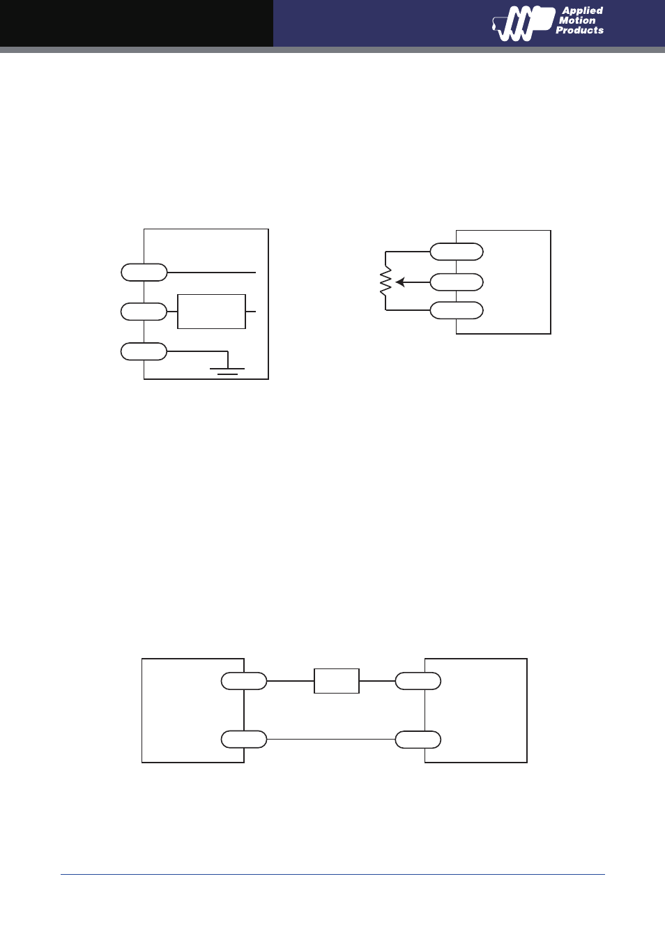
3.3.4 AIN Input
The SSM23Q/IP drives have an analog input (AIN) which can accept a signal range of 0 to 5 volts.
The drive can be configured to operate at a speed or position that is proportional to the analog
signal. Use the Step-Servo Quick Tuner software to set the signal range, offset, dead-band and
filter frequency. The SSM23Q/IP provides a +5 volt 100mA limit voltage supply that can be used to
power external devices such as potentiometers. It is not the most accurate supply for reference,
for more precise readings use an external supply that can provide the desired accuracy.
3.3.5 Programmable Output
The SSM23Q/IP drives feature one optically isolated digital output (OUT). This output can be set
to automatically control a motor brake, to signal a fault condition, to indicate when the motor is
moving or to provide an output frequency proportional to motor speed (tach signal). Or the output
can be turned on and off by program instructions like Set Output (SO). The output can be used to
drive LEDs, relays and the inputs of other electronic devices like PLCs and counters. The OUT+
(collector) and OUT- (emitter) terminals of the transistor are available at the connector. This allows
the output to be configured for current sourcing or sinking.
Diagrams of various connection types follow.
Do not connect the output to more than 30 volts. The current through the output terminal
must not exceed 100mA.
+5v
AIN
GND
100 mA limit
Signal
Conditioning
inside drive
I/O Connector
Ω
+5v OUT
AIN
GND
1 - 10k
pot
SSM23
Connecting a Potentiometer
to the Analog Input
+
-
OUT+
OUT-
5 - 24
volt DC
Power
Supply
Connecting a Sinking Output
Load
SSM23