The step (step) and direction (dir) inputs, 18 stm17 hardware manual – Applied Motion STM17C-3CE User Manual
Page 18
The Step (STEP) and Direction (DIR) Inputs
The STM17 drive+motors include two high-speed inputs called STEP and DIR. They accept 5 to 24 volt single-ended or
differential signals, up to 2 MHz. Typically these inputs connect to an external controller that provides step & direction
command signals. You can also connect a master encoder to the high-speed inputs for “encoder following” applications.
Or you can use these inputs with Wait Input, If Input, Feed to Sensor, Seek Home and other SCL or Q commands.
Note: If current is flowing into or out of an input, the logic state of that input is low or closed. If no current is flow-
ing, or the input is not connected, the logic state is high or open.
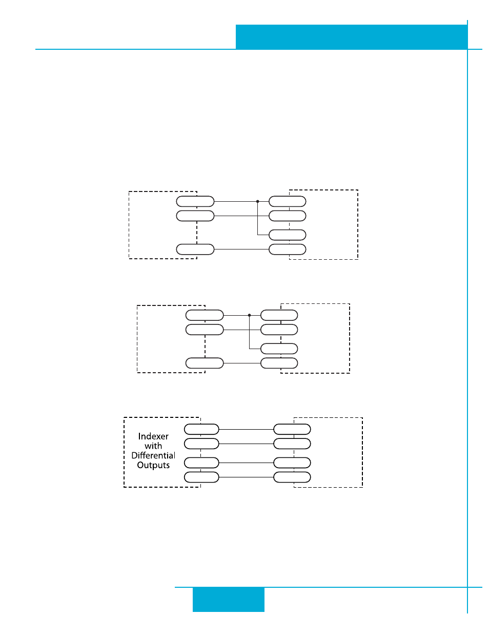
Example connection diagrams:
Connecting to indexer with Sinking Outputs
Connecting to indexer with Sourcing Outputs
Connecting to Indexer with Differential Outputs
(Many High Speed Indexers have Differential Outputs)
STM17
DIR+
DIR
DIR-
STEP+
STEP
STEP-
Indexer
with
Sinking
Outputs
5-24 VDC
STM17
DIR+
DIR+
DIR-
DIR-
STEP+
STEP-
STEP+
STEP-
STM17
DIR-
DIR+
STEP-
STEP+
Indexer
with
Sourcing
Outputs
STEP
5-24 VDC
DIR
18
STM17 Hardware Manual
920-0034 rev A
9/30/2010