The digital output, 22 stm17 hardware manual, Stm17 – Applied Motion STM17C-3CE User Manual
Page 22
The Digital Output
The STM17 drives feature one optically isolated digital output. This output can be set to automatically con-
trol a motor brake, to signal a fault condition, to indicate when the motor is moving or to provide an output
frequency proportional to motor speed (tach signal). The output can also be turned on and off by program
instructions like Set Output. The output can be used to drive LEDs, relays and the inputs of other electronic
devices like PLCs and counters. The “OUT+” (collector) and “OUT-” (emitter) terminals of the transistor are
available at the connector. This allows you to configure the output for current sourcing or sinking.
Note: If current is flowing into or out of an output, the logic state of that output is low or closed. If no current is
flowing, or the output is not connected, the logic state is high or open.
Do not connect the output to more than 30VDC.
The current through the output terminal must not exceed 40mA.
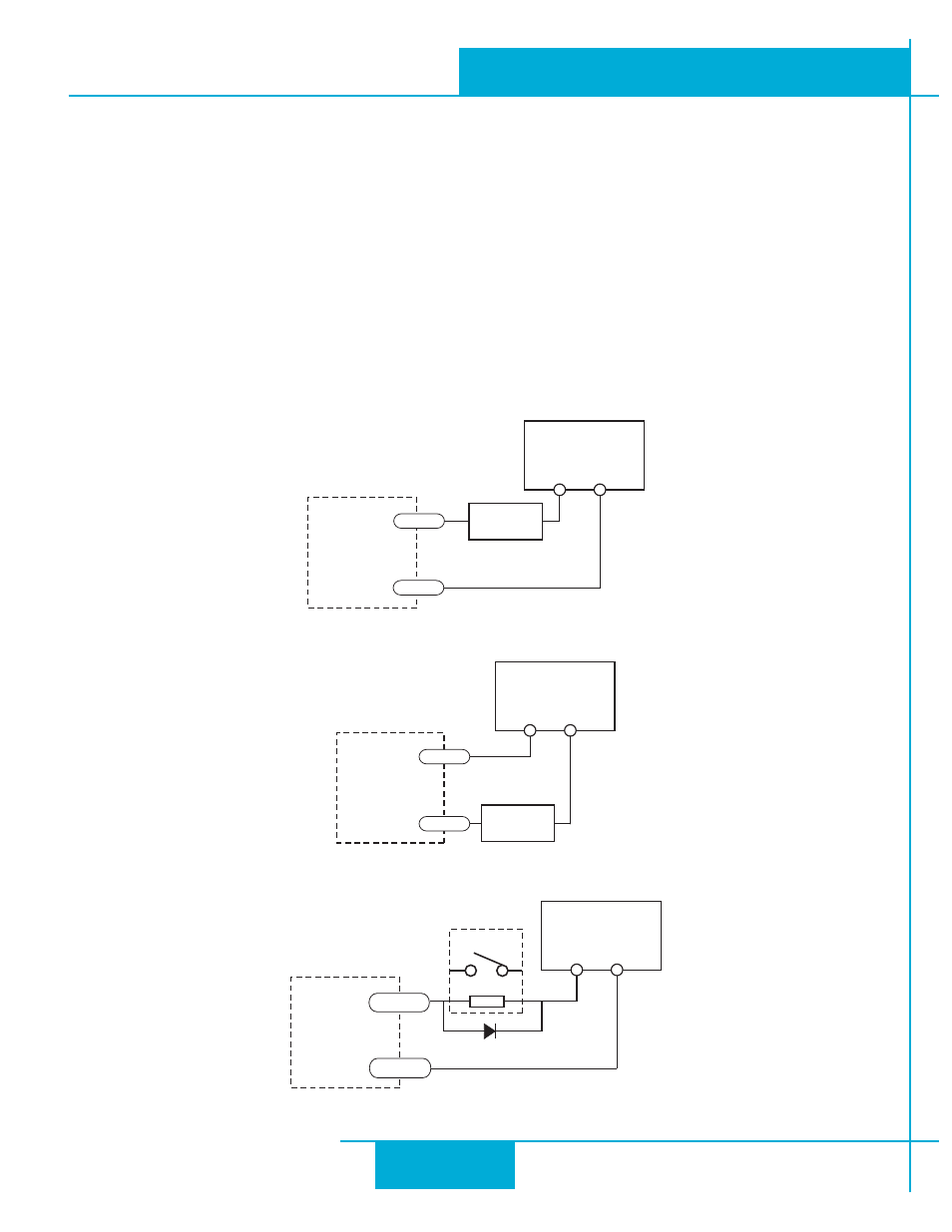
Example connection diagrams:
Connecting a Sinking Output
Connecting a Sourcing Output
Driving a Relay
STM17
5-24 VDC
Power Supply
+
–
Load
OUT-
OUT+
5-24 VDC
Power Supply
+
–
OUT-
OUT+
STM17
Load
STM17
1N4935 suppression diode
5-24 VDC
Power Supply
+
–
relay
OUT-
OUT+
22
STM17 Hardware Manual
920-0034 rev A
9/30/2010