The enable (en) digital input, 20 stm17 hardware manual – Applied Motion STM17C-3CE User Manual
Page 20
The Enable (EN) Digital Input
As mentioned in the previous section, the high-speed STEP and DIR inputs are designed for high speed op-
eration. The Enable digital input is designed for low speed digital input operation between 5 and 24 volts DC.
Note: If current is flowing into or out of an input, the logic state of that input is low or closed. If no current is
flowing, or the input is not connected, the logic state is high or open.
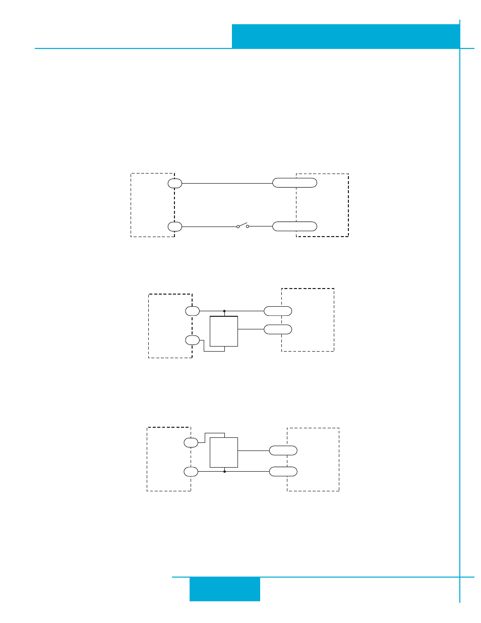
Example connection diagrams:
Connecting the Input to a Switch or Relay
Connecting an PNP Type Proximity Sensor to an input
(When prox sensor activates, input goes low).
Connecting an NPN Type Proximity Sensor to an input
(When prox sensor activates, input goes low).
STM17
Switch or Relay
(closed = logic Low)
EN-
EN+
5-24
VDC
Power
Supply
-
+
NPN
Proximity
Sensor
output
+
–
STM17
5-24
VDC
Power
Supply
EN-
EN+
-
+
5-24
VDC
Power
Supply
PNP
Proximity
Sensor
output
+
–
-
+
STM17
EN-
EN+
20
STM17 Hardware Manual
920-0034 rev A
9/30/2010