3 inputs and outputs, 1 connector pin diagram – Applied Motion TXM24Q-1AG User Manual
Page 15
15
Rev. D
920-0087
TXM24 RS232/485 Hardware Manual
3.3 Inputs and Outputs
The TXM24 has three types of inputs:
• High speed digital inputs for step & direction commands or encoder following, 5 to 24 volt logic
• Low speed digital input for other signals, 5 to 24 volt logic
• Analog input for analog speed and positioning modes
All drives include 3 digital inputs and 1 analog input
• STEP & DIR are high-speed digital inputs for commanding position. Quadrature signals from
encoders can also be used. When not being used for the Step & Direction function these
inputs can be used for CW & CCW Limit, CW & CCW Jogging and Run/Stop & Direction
Velocity modes.
• EN is a low speed software programmable input and can be used for Motor Enable and/or
Alarm Reset. This input can also be connected to a sensor, switch or other device for use with
Wait Input (WI), Seek Home (SH), Feed to Sensor (FS), On Input (OI) and other commands.
• AIN is an analog input for a velocity or position command signal. It can accept 0-5 volts and
has gain, filtering, offset and dead-band settings.
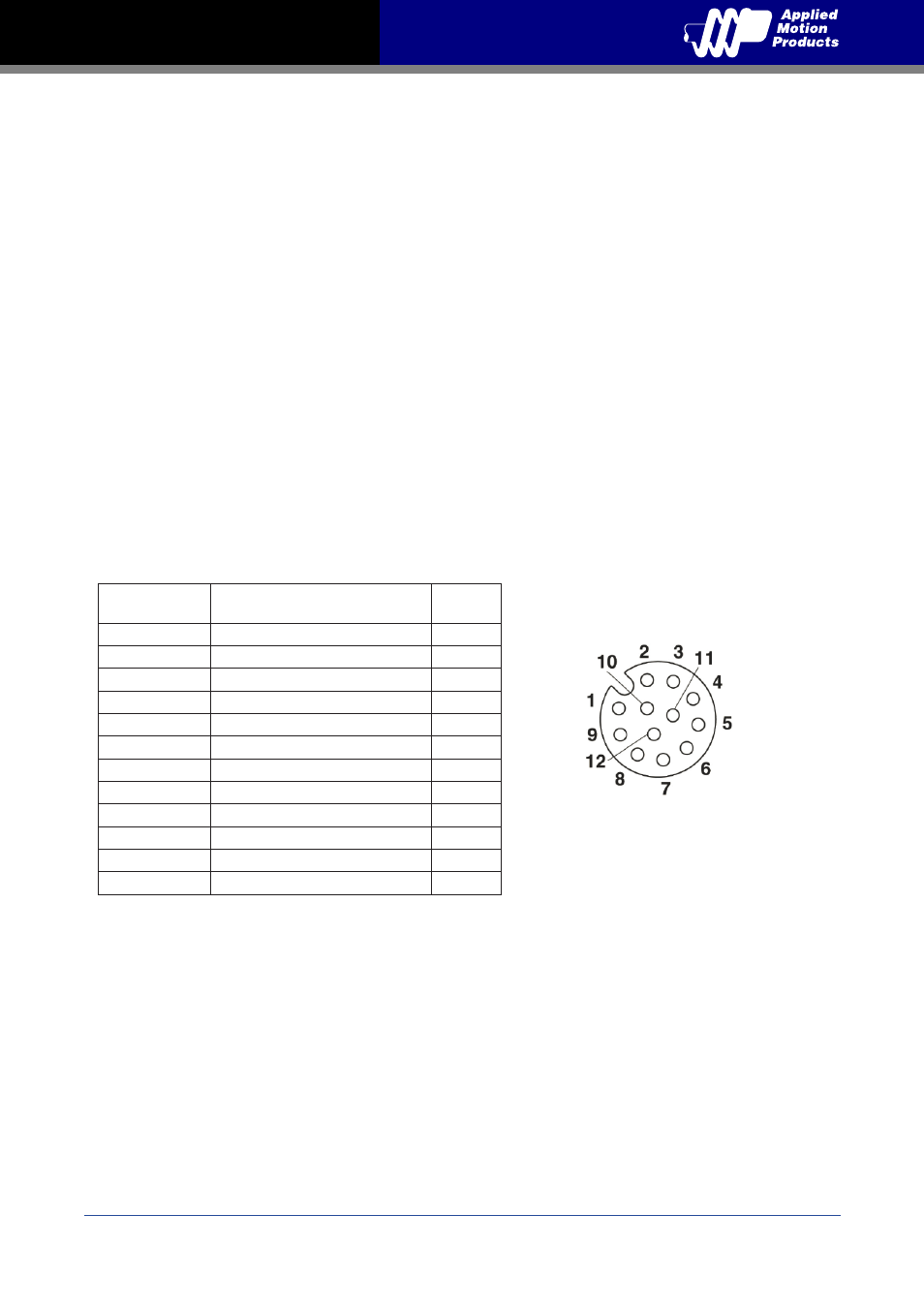
3.3.1 Connector Pin Diagram
IO
Signal
Color of mating cable
Applied Motion P/N 3004-290-5M
Pin no.
Step+
BN
1
Step-
WH
3
Dir+
PK
5
Dir-
GY
8
En+
YE
6
En-
GN
4
OUT+
GYPK
11
OUT-
RDBU
12
+5V
RD
9
AIN
VT
10
GND
BK
7
N/C
BU
2
View of motor side connector