2 block diagram, Txm24s/q, I/o configurations – Applied Motion TXM24Q-1AG User Manual
Page 4
4
Rev. D
920-0087
TXM24 RS232/485 Hardware Manual
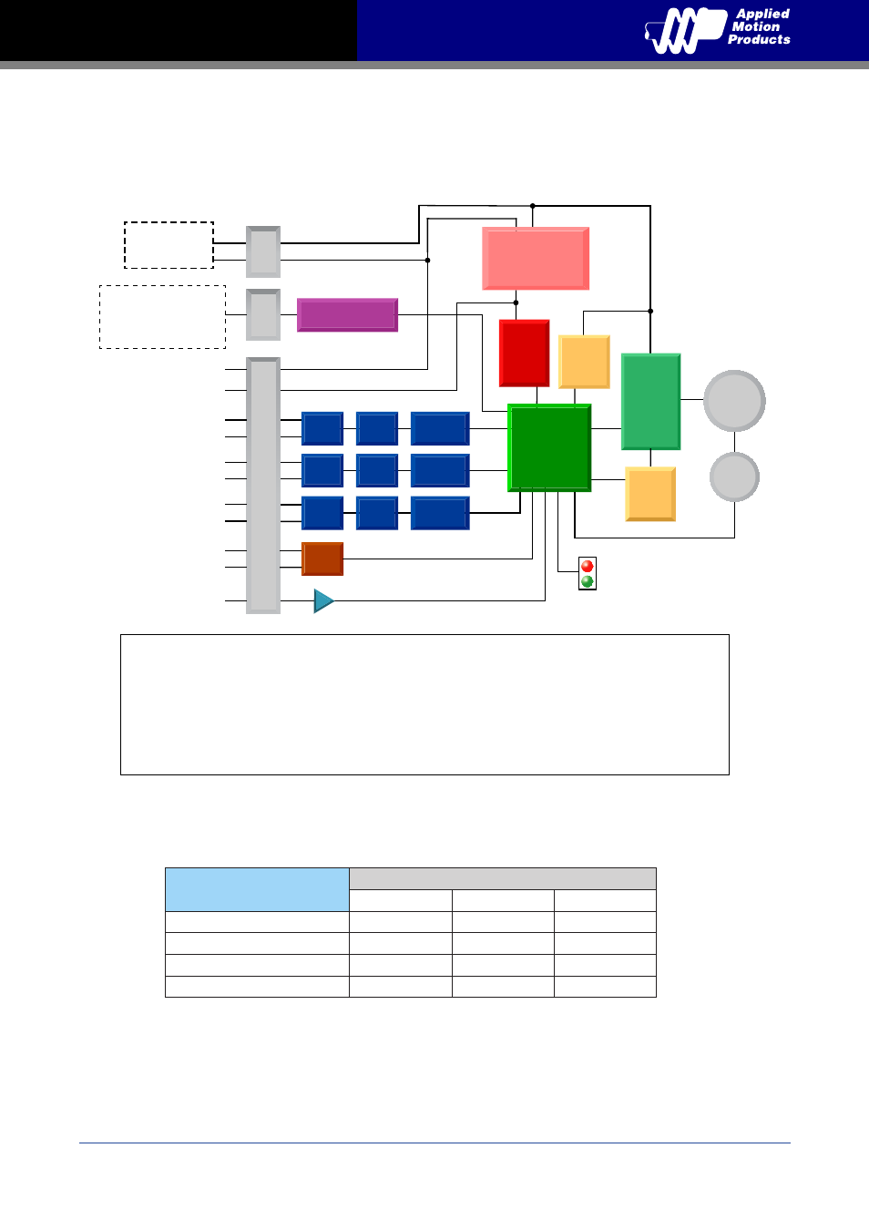
1.2 Block Diagram
Block Diagram
MOSFET
PWM
Power
Amplifier
12 - 70 VDC
External
Power Supply
Voltage
Temp
Detect
Over
Current
Detect
motor
encoder
5 Volt DC
Power Supply
DSP
Driver
Controller
3.3VDC
Internal
Logic
Supply
TXM24S/Q
Optical
Iso
I/O Connector
+
Optical
Iso
Optical
Iso
STEP+
+5VDC (100mA max)
GND
Digital
Filter
Digital
Filter
Digital
Filter
Software
Filter
Software
Filter
Software
Filter
STEP (5 to 24 volts)
Step
CW step
A quadrature (encoder following)
CW limit
CW jog
Start/stop (oscillator mode)
General purpose input
DIR (5 to 24 volts)
Direction
CCW step
B quadrature (encoder following)
CCW limit
CCW jog
Direction (oscillator mode)
General purpose input
EN (5 to 24 volts)
Enable
Alarm/fault reset
Speed 1/speed 2 (oscillator mode)
General purpose input
I/O Configurations
Status
AIN
Optical
Iso
RS-232 or RS-485
Comm Conn
Power Conn
GND
+5V
STEP-
DIR+
DIR-
EN+
EN-
OUT+
OUT-
RS-232
TX,RX,GND
or
RS-485
RX+,RX-,TX+,TX-,GND
-
OUT (30V, 100mA)
Fault
Motion
Tach
In position
Brake
General purpose programmable
Model
Communications
RS-232
RS-485
Modbus/RTU
TXM24S-1AG, TXM24S-3AG
TXM24S-1RG, TXM24S-3RG
TXM24Q-1AG, TXM24Q-3AG
TXM24Q-1RG, TXM24Q-3AG