Applied Motion TXM24Q-1AG User Manual
Page 16
Advertising
16
Rev. D
920-0087
TXM24 RS232/485 Hardware Manual
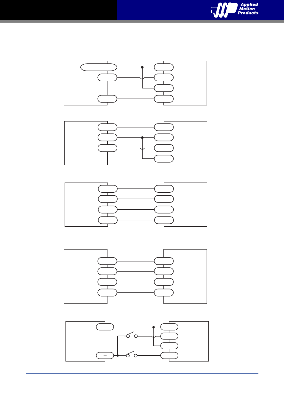
3.3.2 STEP & DIR Digital Inputs
The diagrams below show how to connect the STEP & DIR Inputs to various commonly used
devices.
+5v to +24v out
DIR
STEP
DIR+
DIR-
STEP+
STEP-
Indexer
with
Sinking
Outputs
Connecting to Indexer with Sinking Outputs
TXM24
DIR
COM
STEP
Indexer
with
Sourcing
Outputs
DIR+
DIR-
STEP+
STEP-
Connecting to Indexer with Sourcing Outputs
TXM24
DIR+
DIR-
STEP+
DIR+
DIR-
STEP+
STEP-
STEP-
Indexer
with
Differential
Outputs
Connecting to Indexer with Differential Outputs
Many high-speed indexers have differential outputs
TXM24
A+
A-
B+
STEP+
STEP-
DIR+
DIR-
B-
Master
Encoder
Wiring for Encoder Following
TXM24
DIR+
DIR-
STEP+
STEP-
5 - 24
volt DC
Power
Supply
Using Mechanical Switches
+
direction switch
run/stop switch
(closed = run)
TXM24
Advertising
This manual is related to the following products: