Cvm-c10 instruction manual, Power supply v, L1 l2 – CIRCUTOR CVM-C10 Series User Manual
Page 20
Advertising
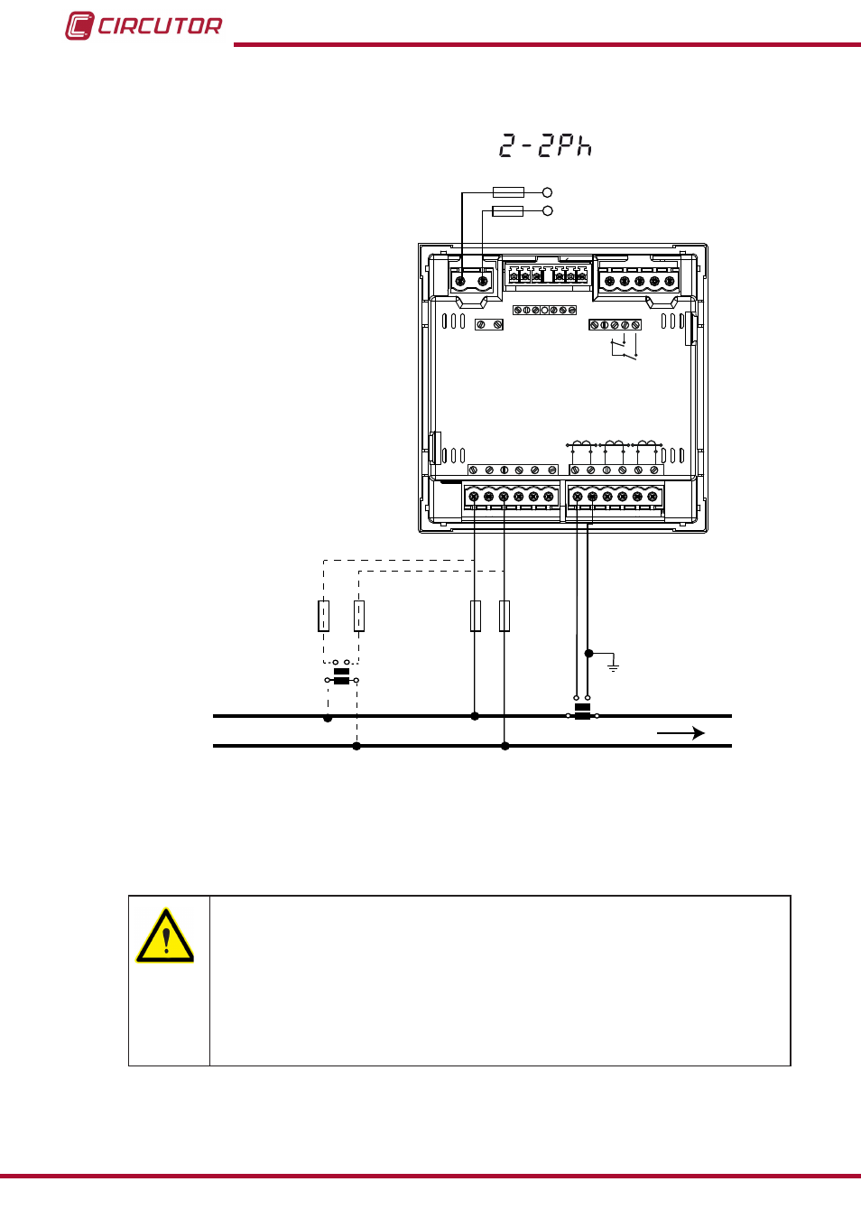
3�4�9�- Measuring Single-Phase Networks, phase to phase, with a 2-wire connection,
CVM-C10-ITF, CVM-C10-MC and CVM-C10-mV models�
Measurement system:
Power
Supply
V
L1
V
L2
L1
L2
POWER SUPPLY
INPUTS
A
(+) B(-)
GND
RS485
S1
S2
S1
S2 S1
S2
L1
P1
P2
L2
L3
300V ~
Ph-N
Ph-Ph
520V ~
N
V
L3
L2
V
L1
V
P1
P2 P1
P2
I1 I2
OUTPUTS
Rc R2 R1
Tc T2 T1
S0- S0+ S0+
V
L1
V
L2
a
b
A
B
S1
S2
P1
P2
LOAD
Figure 11: Measuring Single-Phase Networks, phase to phase, with a 2-wire connection, CVM-C10-ITF, CVM-C10-MC
and CVM-C10-mV models�
CVM-C10-ITF model:
The transformer secondary value must be 5A or 1A
CVM-C10-MC model:
The MC transformer secondary value is set to 0.250 A (fixed value)
CVM-C10-mV model:
The transformer secondary value must be 0.333 V
20
CVM-C10
Instruction Manual
Advertising