Electrical connection – Computronic Controls Sentinel 300P User Manual
Page 5
Sentinel 300P installation, operation & maintenance
ci0039 p5/12 issue 9 2015-09-04
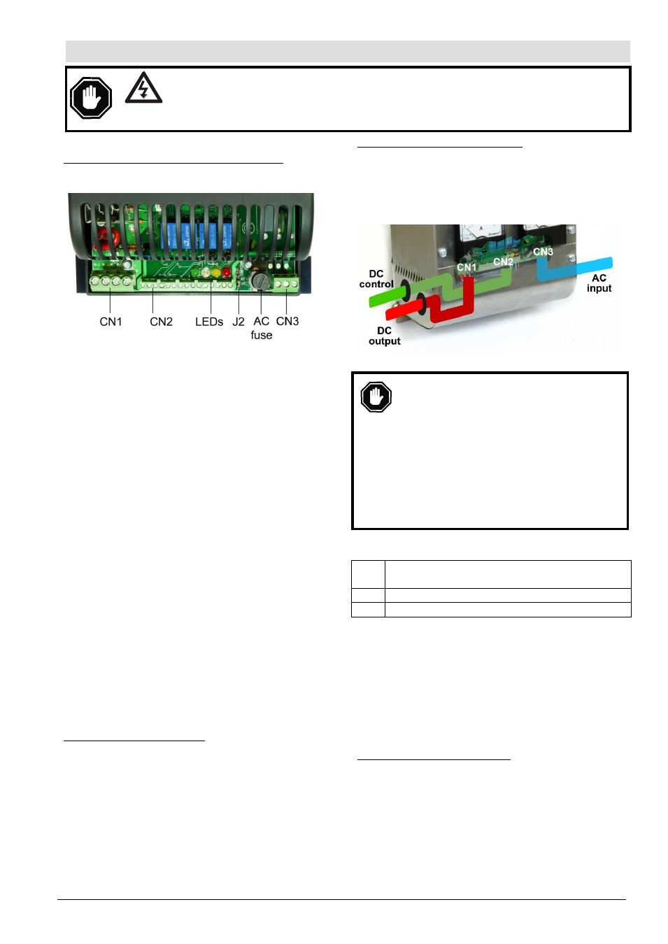
Connection - General
SNTL300P open-frame (protective cover) models:
Open frame models use 3 circuit board mounted screw
terminal blocks:
CN1: a 4-way block for connection of the DC Charge
Output. Use a 5 mm/0.2 in. flat-head screwdriver
to tighten/loosen the terminals. For the DC Output
(10 Amp max), use 4.0mm²/13 AWG or larger
connecting wire. For details of fusing, see the Battery
DC Charge Output section following.
CN2: a 15-way block for connection of DC control
signals: DC voltage sensing, temperature compensation
remote sensor, control inputs and outputs. Use a
2.5mm/ 0.1 in. flat-head screwdriver to tighten/ loosen
the terminals. Use 1mm²/17 AWG or larger wire for
these connections. This connector block also includes
terminals for RS485 and optional CAN (SAE J1939)
communications: use wiring in accordance with the
appropriate data communication standard (typically a
twisted pair, with shield grounded at one end only).
CN3: a 3-way block for connection of the mains AC live
and neutral power supply. Use a 5mm/0.2in flat-head
screwdriver to tighten/loosen the terminals. The AC
supply ground/earth must be connected to a separate
M4 stud marked FG (Frame Ground) on the charger
chassis. For all AC supply/ground wiring, use 1mm²/
17 AWG or larger wire conductors rated for 90°C/194°F.
An AC fuse holder is located next to CN3: for fuse
details, see the AC Input (power supply) section
following.
4 LEDs (coloured green, blue, yellow, red) above the
terminal blocks provide indication of configuration and
operating status. Circuit board jumper J2 is for the
configuration of automatic temperature compensation.
For full details of LED and J2 operation, see Configuration
and Operation section.
ESNTL300P (enclosed) models
Enclosed ESNTL models have the same circuit board
terminal numbering as SNTL models.
Access to the screw terminals, and access for the wiring
harness (via cable glands), is detailed in the Dimensions
and Assembly section.
All models
– wire harness separation
For all models, wire connections for the DC charge output
(connector block CN1), DC control signals (CN2) and AC
input supply (CN3) must be physically separated, e.g.
using separate wiring harnesses to each connector block,
separately routed through the case/panel. For enclosed
ESNTL models, use separate cable gland access:
Battery DC Charge Output
Before DC connection or disconnection:
Ensure AC supply input is isolated.
Disconnecting the batteries while the
AC supply is live can result in sparking at
the battery terminals, ignition of battery
gasses and serious personal injury.
Check that the charger has been configured
for compatibility with the battery type &
voltage (see Configuration section below).
Incompatibility may result in damage to
the charger, batteries and serious
personal injury.
Connect the Sentinel output to the battery terminals,
observing the warnings above and the correct DC polarity:
CN1
pin
Function
1, 2 + DC charge output
3, 4
– DC charge output
All (E)SNTL300P models include self-resetting electronic
protection against reverse polarity, overload and short-
circuit faults. In the event of such faults, the DC output
switches off, protecting the charger. After a 4 second delay,
Sentinel checks the DC output connection: if the fault has
cleared, the output automatically re-activates; if the fault is
still present, the output deactivates again, and the
delay/check cycle repeats.
If the DC output fails to re-activate after a fault has cleared,
contact your charger supplier for further advice.
Float & AutoBoost output voltages
The DC charge output can be configured to give one of
several 12 or 24V ‘charge profiles’, each with Float and
AutoBoost voltages that are optimised for the battery type
and number of cells.
Charge profile configuration is either via circuit board DIP
switches, or (on LCD models) using display menus and
control keys: see Configuration section below. Charge
profile can also be set using the Computronic SNTL300P-
PCSUITE PC software tool and RS485 communication link.
For full details, see separate software manual ref. ci0042.
Electrical Connection
DANGER !
HIGH VOLTS
WARNING: DANGER OF INJURY OR DEATH. During normal operation, Sentinel is
connected to high voltage AC circuits. Before connection, disconnection or handling of
these chargers, ensure isolation of all AC power supplies. Connection or disconnection
with live wiring can also cause hazardous sparking and component damage.