Electrical connection (cont.) – Computronic Controls Sentinel 300P User Manual
Page 6
Sentinel 300P installation, operation & maintenance
ci0039 p6/12 issue 9 2015-09-04
Battery DC voltage sense
CN2
pin
Function
1
+ DC voltage sense
2
– DC voltage sense
These terminals are used to accurately measure battery
voltage, independently of the voltage drop that can occur
between the battery and DC charge output (particularly at
higher charge currents, and with longer cables).
Accurate measurement of battery voltage allows Sentinel
to automatically compensate for volt drops in the charging
circuit, by increasing charge voltage.
Connect the battery DC Sense terminals to battery
positive and negative using 1mm²/17 AWG or larger wire.
TC Temperature Compensation Sensor
CN2
pin
Function
3
TC (temperature compensation) sensor
4
Ground (for RTC sensor)
These terminals allow optional connection of a Computronic
RTC temperature sensor. With the sensor connected, and
the sensor head positioned to give the most accurate/
representative measurement of battery temperature,
Sentinel automatically varies DC output voltage for optimal
charging. Circuit board jumper J2, located between terminal
blocks CN2 and CN3, must also be in the correct position:
J2 jumper
position /
mode
Description
External /
disabled
(Factory default setting). Temperature
compensation is enabled automatically when a
remote RTC sensor is connected. For each
1°C change in ambient temperature above or
below 20°C (within the range -10 to +50°C),
output voltage automatically varies by 3mV
per cell. Increasing ambient temperatures
cause decreasing output voltages; decreasing
ambient temperatures cause increasing output
voltages.
If no RTC sensor is connected, temperature
compensation is automatically disabled and
the output voltage does not vary with ambient
temperature.
Sensor connection and operating status is
indicated by a blue LED
– see Operation
section for details.
Internal
Not for customer use. Temperature
measurement by internal sensor, for factory
calibration only.
CN2 terminals 3 and 4 are designed for connection to a
Computronic RTC sensor only. DO NOT connect other
types of temperature sensor, such as thermocouples,
thermistors or resistance probes.
The standard RTC sensor (part code 42.70.3619) includes
a 3 metre lead assembly. Non-standard lead lengths are
available to special order.
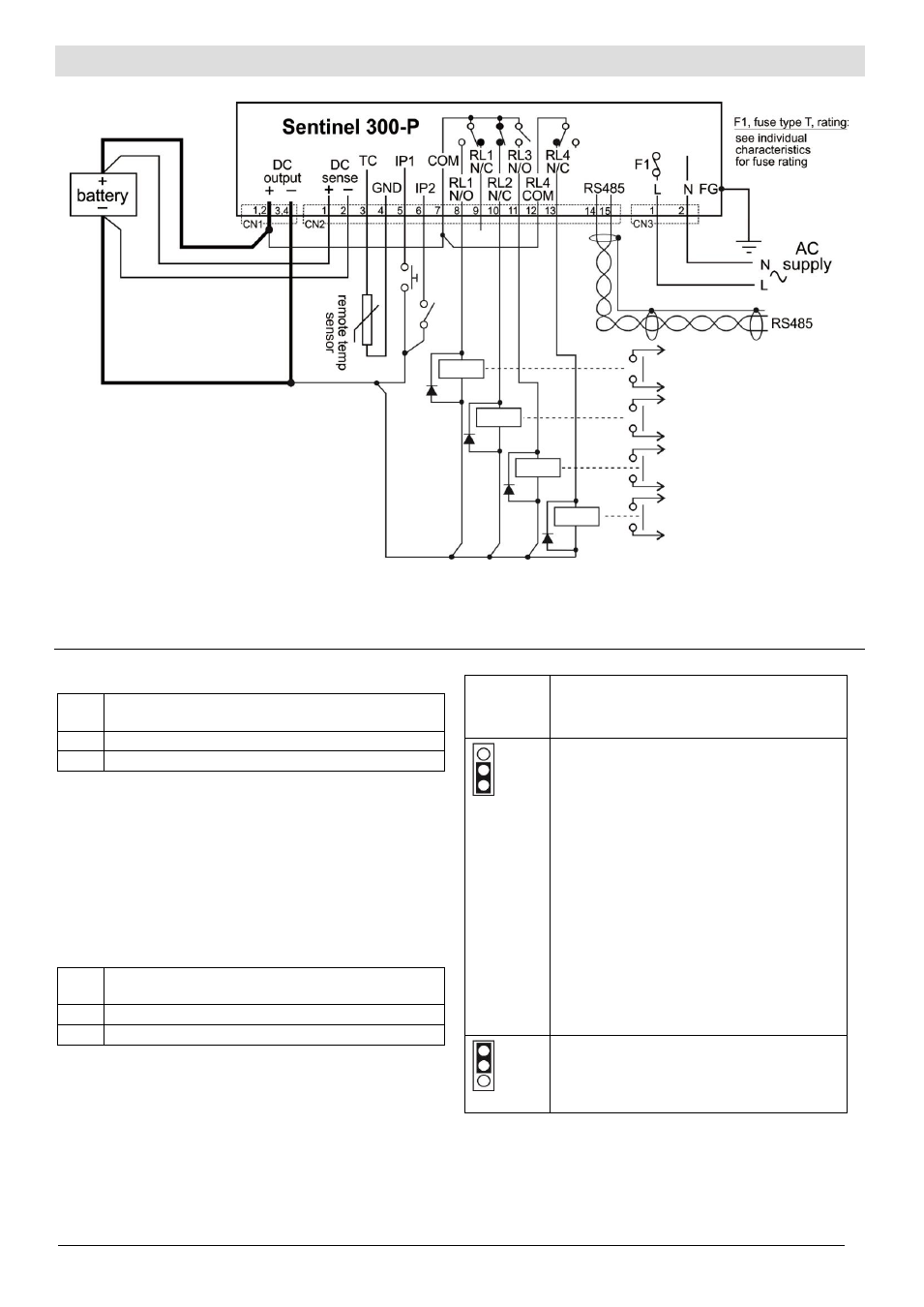
Electrical Connection (cont.)
Typical Connection:
Notes:
1. AC input fusing (F1): replaceable, circuit board mounted fuse, rating as shown on the product label.
2. DC output fusing: all models include a self-resetting electronic output fuse.
3. DC output is isolated from chassis.
4. connection shown for standard configurations with output RL4. (RL4 is not available on units configured for CAN communication.)