1 audio and gpio installation – Doremi ShowVault / IMB User Manual
Page 12
CRT.OM.001420.DRM
Page 12 Version1.6
Doremi Labs
4.1 Audio and GPIO Installation
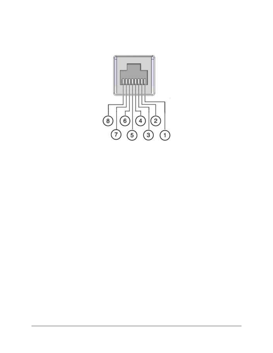
4.1.1 Audio and GPIO Pin-Out Information
Figure 9: RJ45 Pinout Example
4.1.2 Audio CAT5 Cable Installation
Plug one CAT5 cable end into the top AES slot (RJ-45 connector) for audio channels 1-
8.
Plug the other end of the CAT5 cable in the audio processor.
Take another CAT5 cable end and plug it into the bottom AES slot (RJ-45 connector) for
audio channels 9-16.
Plug the other end of the CAT5 cable adapter in the audio processor.
4.1.3 GPIO CAT5 Cable Installation
Plug one CAT5 cable end from the GPI slot into whichever automation controller is
available or required.
Take another CAT5 cable and plug it from the GPO slot into whichever automation
controller is available or required.