Junger Audio b42 - Dynamics Processor User Manual
Page 23
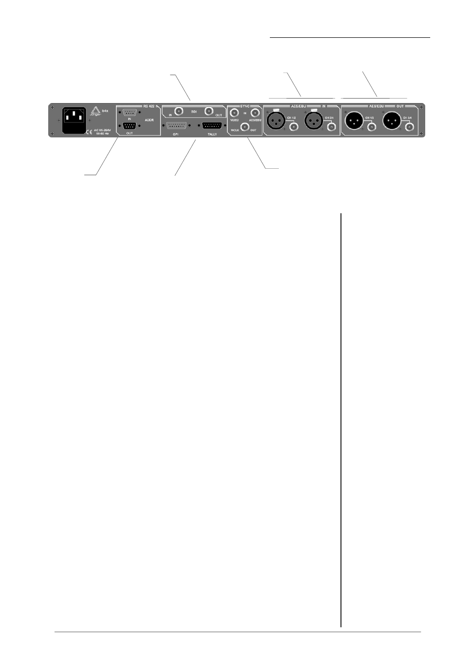
4. LOCATION OF PARTS AND CONTROLS
4.2.
REAR PANEL
SDI IN-/
OUTPUT
DIGITAL
INPUTS
DIGITAL
OUTPUTS
SYNC IN
SERIAL
REMOTE
IN/OUT
GPI REMOTE
IN/OUT
fig. 2: rear panel b42
POWER INPUT
IEC mains input connector 100-240V, 50/60 Hz with integrated fuse
REMOTE
serial remote interface RS-422
connector:
9pin SUB-D, input - female, output - male
GPI
paralle remote interface
TALLY-out
open relais contact
connector:
15pin SUB-D, male
GPI-in
+3,5…+30V potential-free
connector: 15pin SUB-D, female
SYNC
AES/EBU
input for ext. sync signal (AES 3 format, 75 Ohm, unbal)
connector: BNC socket
VIDEO
input for video sync signal (blackburst, 75 Ohm, unbal)
connector: BNC socket
W-CLOCK
output for wordclock sync signal, TTL level, unbal.
connector: BNC socket
SDI IN / OUT (only if installed!)
Input/output for serial digital video (ITU-R BT.601, SMPTE 272M-A)
with embedded audio
Format:
270 Mb/s, 525/625 line rate, 75 Ohm,
connector: BNC socket
DIGITAL IN
input for AES/EBU standard format
connector: XLR female panel jack
1- ground, 2-3 signal, balanced
connector: BNC socket 75 Ohm, unbalanced
DIGITAL OUT
output for AES/EBU standard format
connector: XLR male panel jack
1- ground, 2-3 signal, balanced , 4 Vpp
connector: BNC socket 75 Ohm, unbalanced, 0.5V pp
Operation manual b42, chapter 4 -location of parts and controls - page 4-3