Control and display elements – Junger Audio d02 - Digital Dynamics Processor User Manual
Page 17
3. CONTROL AND DISPLAY ELEMENTS
CONTROL AND DISPLAY
ELEMENTS
All functions of the digital dynamics processor d 02 are
activated by buttons. The front panel shows easily recognizable
function groups.
3
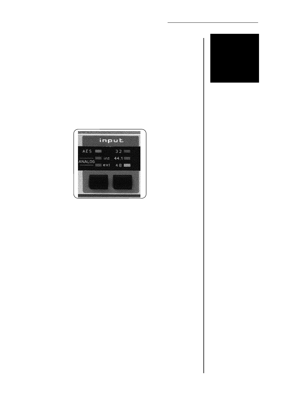
input
By pressing the left button in the input section the required input signal
can be selected. Each time the button is pressed the input selection is
changed and one of the three LED's above the button lights to show
the newly selected input.
When the AES LED is lit the unit processes the AES/EBU format digital
audio signal applied to its AES/EBU input connector.
When ANALOG INT LED is lit the unit processes the analogue input audio
signal aplied to its analogue input connectors, and the sampling frequency
at which the A/D-converter operates is generated internally.
When ANALOG EXT LED is lit the unit uses the same analogue input
audio signal as when ANALOG INT is selected, but now the sampling
frequency at which the A/D converter operates is determined by the
external word clock or AES/EBU input signal which is fed into the unit.
To the right of the input indicator are three LEDs which shows the sample
rate of the selected input. If a given external digital signal (input signal or
wordclock) has the correct sample rate, the device automatically
synchronizes to that frequency and a yellow light appears on the LED. All
LEDs will blink red if the input signal is lacking or the sample rate is outside
the admissible tolerance range.
With internal synchronisation (ANALOG intern) the sample rate display is
green and the frequency can be changed with the button below.
3-1