Junger Audio d02 - Digital Dynamics Processor User Manual
Page 21
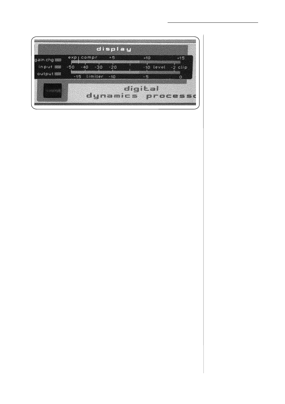
3. CONTROL AND DISPLAY ELEMENTS
The two channel LED display has three display modes (input level, output
level and gain change). Press the button in the display section to change
the display mode. The selected display mode is indicated by the lighting of
the appropriate LED above the display button and to the left of the display
meters. For better visibility each display mode has its own LED colour and
level meter colour.
display
Green shows the input level and yellow the output level. The scale located
between the two bars indicates the levels. The display which ranges from -50
... 0 dBFS (dB Full Scale) refers to the digital reference level, with a
resolution of 2 dB in the upper section. This does not allow a precise
adjustment, but it does give an indication of the existence and the level of
digital input and output signals.
A peak hold function is available for input and output which makes improved
registration of a momentary peak level possible.
If excessive level at the input occurs when the input level display is selected
(if digital audio samples at the maximum permissable positive or negative
sample value occur at the digital input) then the red clip-LED at the
extreme right-hand end of the level meter lights up and indicates overloads
which are already present in the input signal.
When viewing the OUTPUT level the clipping LED does not light since
the limiter is ON and ensures that the maximum output signal level can not
exceed the preset reference level.
The level meter display is a digital meter without integration time, and
records every successive digital sample value.
The third display mode, gain change, shows the current control levels of
the limiter and compressor in dB.
The compressor works to reduce overall dynamic range by insertion of
additional gain for lower level signals (ie no gain reduction). The scale
above the upper meter bar shows the additonal gain inserted by the
compressor. Lighting of LED's in the meter starts on the left and moves
torwards the right as more additional gain is applied.
The limiter works to reduce the level of high level input signals so that they
do not exceed the preset reference maximum level. The scale below the
lower meter bar shows the level reduction by the limiter. Lighting of LED's
in the meter starts on the right and moves torwards the left as the amount of
level reduction (limiting) required increases.
A red LED is visible in the compressor gain display , which indicates the
maximum permissable value of compressor gain. This value can be
changed in the range +2dB to +15dB (see section on operation of the
compressor on page 10 for details of how to change the maximum
permissable compressor gain).
3-5